Sections:
System Modelling |
One-Line Diagram |
Reactance/Impedance Diagram
System Modelling
Pointers.
1. Base kV and Base kVA is selected in one part of the system. The base values for a three-phase system is equal to the line-to-line kV and three-phase kVA or MVA.
2. For other parts of the system, e.g., on the other side of the transformers, the base kV for each part is determined by the line-to-line voltage ratios of the transformers. The base kVA is the same throughout.
3. Impedance information available for three-phase transformers are usually in per unit or per cent on the base determined by the ratings.
4. For three (3) single-phase transformes connected as a three-phase unit, the three-phase ratings are determined from the single-phase rating of each individual transformer. Impedance in per cent for the three-phase unit is the same as that for each individual transformers.
5. Per cent impedance given on a base other than that determined for the part of the system in which the element is located must be changed to the proper base by using

Sections:
System Modelling |
One-Line Diagram |
Reactance/Impedance Diagram
One Line Diagram
Here are the most common symbols used for solving problems on power systems

Thus, a simple power system should consist a generating unit, a transmission line, a set of transformers and a load, usually a motor. Machines, such as generators, motors, and transformers are indicated on the manner in which they are connected for clarity, especially when drawing the zero-sequence components.

Sections:
System Modelling |
One-Line Diagram |
Reactance/Impedance Diagram
Reactance / Impedance Diagram
Definition.
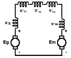
The reactance/impedance diagrams are simple representations of the given power system. The rotating machines are represented by a circle and a respective internal reactance. Line impedances are indicated by the common symbol for impedance: resistive, inductive or capacitive. Transformers are symbolized by their respective leakage reactances, depicted similarly as line impedances. Usually, in transformers, the magnetizing circuit is deemed neglible in power system computations, unless required for inclusion.
 Thus, for the given power system, above, the equivalent reactance / impedance diagram would be as given on the right. Where:
Eg = EMF of generator
Em = EMF of motor
X"g = Internal Reactance of generator
X"m = Internal Reactance of motor
X"T1 = Leakage Reactance of Transformer No. 1
X"TL = Reactance of Transmission Line
X"T2 = Leakage Reactance of Transformer No. 2
 Example Problem

