|
|
| Home |
| PPD |
| Sites |
| ABdA |
| Help |
|
WEEK 11: DISTRIBUTION: DISTRIBUTION PRACTICES Sections: Elements | Classifications | Subtransmission | Primary | Secondary Elements of Distribution Systems Distribution includes all parts of an electric utility system between bulk power sources and the consumers' service-entrance equipments. A more limited definition of distribution is that portion of the utility system between the distribution substations and the consumers' service-entrance equipment. In general, a typical distribution system consists of (1) subtransmission circuits with voltage ratings usually between 12.47 and 25 kV which deliver energy to the distribution substations; (2) distribution substations which convert the energy to lower primary system voltage for local distribution including facilities for voltage regulation of the primary voltage; (3) primary circuits or feeders usually operating between 4.16 to 34.6 kV and supplying the load in a well-defined geographical area; (4) distribution transformers in ratings from 10 to 2500 kVA which maybe installed on poles, grade-level pads, or in underground vaults near the consumers and transform the primary voltages to utilization voltages; (5) secondary circuits at utilization voltage which carry the energy from the distribution transformers; and (6) service drops which deliver the energy from the secondary to the users' service-entrance equipment. Voltage Range The function of distribution is to receive electric power from large, bulk sources and to distribute it to consumers at voltage levels and with degrees of reliability that are appropriate to the various types of users. For single-phase residential users, Voltage Range A is defined by ANSI C84.1-1989 as 114/228V to 126/252V at the user's service entrance and 110/220 to 126/252V at the point of utilization. Nominal voltage is 120/240V. Sections: Elements | Classifications | Subtransmission | Primary | Secondary Classifications of Distribution Systems Distribution system maybe classified in various ways: Single-phase loads are almost universally supplied through 120/240-V, three-wire service. Large appliances such as ranges, water heaters and clothes dryer are served at 240V. Lighting, small appliances and convenience outlets are supplied at 120V. In the Philippines, single-phase loads are supplied at the nominal 220-V.
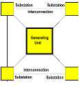
Network - commonly called the grid system, consists of interconnected generating units with radial networks of substations. Multiple - consists of a combination of the above three schemes. It uses two or more circuits which are tapped at each substation. The circuits may be radial or may terminate in a second bulk power source. Series - linear or end-to-end arrangement of substations or distribution poles (used in street lighting). Overhead distribution system are universally used in smaller towns and less-congested areas of larger cities. AS load densities increase, this type of construction becomes unwieldy because of the larger transformers and conductors required. Underground distribution system are popular especially on new residential subdivisions and downtown commercial areas of most cities because of low cost, solid-dielectric cables suitable for direct burial, mass production of pad-mounted distributed transformers and accessories, and mechanized cable-installation methods. Sections: Elements | Classifications | Subtransmission | Primary | Secondary Subtransmission is a part of the utility system which supplies distribution stations from bulk power sources, such as large transmission substations or generating stations. Distribution substations supply primary distribution systems. Subtransmission moves relatively large amounts of power from one point to another, like transmission, and at the same time it provides area of coverage, like distribution. Voltages of subtransmission circuits range from 12 to 245 kV, but levels of 69, 115, and 138 are most common. The use of higher voltages is expanding as higher primary voltages are receiving increased usage. Conductors of ACSR or aluminum have supplanted copper in overhead construction. The size of conductors in subtransmission systems is determined by (a) magnitude and power factor of the load, (b) emergency loading requirements, (c) distance that the load must be carried, (d) operating voltage, (e) permissible voltage drop under normal and emergency loading, and (f) optimum economic balance between installed conductor cost and cost of losses. Scheme of Construction for subtransmission is popularly that or loop and multiple circuit pattern. A vast majority is of overhead construction, much of which are built on city streets as contrasted to private right-of-way. Sections: Elements | Classifications | Subtransmission | Primary | Secondary Primary Systems takes energy from the low-voltage bus of the distribution substations and delivers it to the primary windings of the distribution transformers. Typically, overhead primary distribution systems operate on radial circuits (normally open loops) from the substations outward. Utilities use automatic reclosing feeder breakers and line reclosers to minimize service interruptions. Automation, like SCADA, makes greater use of protective and sectionalizing equipment to minimize the number of customers involved in an outage and to reduce the outage time. Voltage Levels usually the 15-kV distribution class represents 60 to 80% of all primary distribution activity. Most of these systems are not voltage-drop-limited, and cost of higher-voltage laterals and associated equipment needed to cover the load area is greater. Conductors sizes used in primary overhead primaries generally range from No. 2 AWG to 795 kCMil. ACSR and aluminum conductors have almost entirely displaced copper for new construction. For underground primaries, size range from No. 4 AWG to 1000 kCMil. Primary Feed loading varies depending on the primary voltage, load density, emergency loading requirements, etc. Typical peak loads on 15-kV class feeders are 6 to 7000 kVA. Voltage drop in the primary feeder is an important factor in system design. The traditional rule of thumb is to allow a voltage drop of about 5% in the primary of urban and suburban systems at time of peak load. It is very probable, however, that economic system designs have a primary voltage drop smaller than 3%. In rural systems, typically with long lines and light load densities, voltage drop maybe somewhat larger. Sections: Elements | Classifications | Subtransmission | Primary | Secondary Secondary Distribution Systems Secondary Mains operate at utilization voltage and serve as the local distributing main. The scheme of construction is usually that of overhead radial type. Single-phase secondary mains supplying general lighting and small power are usually 3-wire mains operating at 120 V line-to-neutral and 240-V line-to-line. Conductors Sixty feet is the permissible length of three No. 1/0 aluminum secondary mains depends on the load density and on the assumption of evenly distributed loads and 3% drop in the mains, for 15kW/1000 ft., and for 30 kW/1000 ft. this is about 400ft. Widespread ranges and motor-driven appliances establishes an additional limit for flicker at 200 to 300 ft. The three No. 1/0 to 4/0 aluminum single-phase secondary mains should not be replaced by larger conductors to improve secondary-main regulation. Additional transformers should be installed and parts of the existing mains transferred to the new transformers. |