|
|
| Home |
| PPD |
| Sites |
| ABdA |
| Help |
|
WEEK 09: TRANSMISSION: COMPONENT SPECIFICATIONS Sections: Introduction | Methods | Application | Control Accessories Effects of Unregulated Voltage Objectives. The primary object of an electrical system is to provide power users with a supply voltage compatible to their utilization equipment. 1. Resistance loads (stove, iron, heaters) 2. Motor Loads (vacuum cleaner, washing machines, fans, refrigerators) 3. Electronic Loads (radio/television, personal computer) 4. Illumination Loads Sections: Introduction | Methods | Application | Control Accessories 1. STEP-TYPE - using tapped autotransformers, transformers which part of one winding is connected to both the primary and the secondary circuit associated with that winding. The primary (exciter) winding is both electrically and magnetically connected to the secondary (series) winding. The exciter winding is common to both primary and secondary; the series winding is connected in series with load (output) current, Step-type voltage regulators are commonly provided in both single- and three-phase styles. 2. TRANSFORMER LOAD-TAP CHANGERS - a combination of a transformer and the step-type method. Tap changing is usually gang-operated through a three-phase oil switchgear. 3. FIXED / SWITCHED CAPACITOR - used to improve line-voltage profile by connecting a bank of capacitors in shunt. Improving a lagging power factor would reduce line losses and thus improve regulation. Coversely, when used beyond unity, thus leading, will increase the voltage and increase in current. 4. STATIC VAR SYSTEMS (SVS) - involve effectively regulating (or fine tuning) the reactive compensation afforded by the shunt capacitors by virtue of phase-angle firing control of thyristors. The thyristor conduction period will establish the capacitive (leading) current.
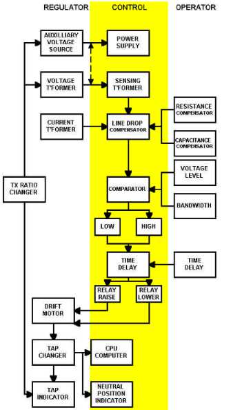
The functions of the typical regulator control are as follow: An auxiliary voltage source, such as a nominal 120-V tertiary winding on the main core and/or a voltage transformer, will be provided to supply power and the signal for deriving the regulator output voltage. This 120 V is scaled down in a sensing transformer which may itself be tapped to facilitate ratio adjustment if the voltage source is not exactly as required. The output of the sensing transformer will, by operator selection, be altered to reflect the voltage drop between the regulator and the load. This drop, which is a function of the load current and the line impedance, is modeled by knowing the current from a current transformer and established line resistive compensation and line reactive compensation parameters. The voltage, now compensated for line drop, is related in a comparator to the desired voltage level as established by a voltage-level setting (the voltage which the regulator is to maintain at its output, expressed on a 120 V base) and a bandwidth (define the limits of acceptable voltage about the voltage-level setting) or tolerable voltage range limits setting. If the compensated voltage exceed the high limit (or is less than the low limit), a time delay (the time duration outside the prescribed band required before tap-changer actuation) is activated. After the preset delay, typically 30 to 60 seconds, a drive motor is powered and runs the tap changer to the next position. Tap-changer motion advances the operation counter, moves the tap position indicator pointer, and causes illumination of a special neutral position indicator light. Of course the new tap position in turn causes a transformer ratio change, altering the input to the sensing transformer and closing the control function loop. Sections: Introduction | Methods | Application | Control Accessories Single-phase regulators in three-phase installations is a very common application. Configuring the regulators in wye, closed delta, and open delta are acceptable alternatives, depending on system conditions. Regulator sizing is a straightforward adaptation of single-phase principles. The various regulator connections utilize the installed kVA of regulators with differing efficiency. For each 1000 kVA of system capacity, the use of ±10% regulators will require total regulator capacity of 100 kVA (grounded wye), 123 kVA (closed delta) and 115 kVA (open delta). In deciding the proper and safe connection for a given application, the following should be considered: (1) third harmonics, (2) system line surges, and (3) line faults.
Parallel connections of regulators is used if and only if sufficient loop impedance exists to limit circulating currents, based on the maximum difference in the voltages of the two circuits V1 and V2. Equally important, the percent impedances of the two circuits must be equal or very close so that circulating current does not exceed 10% of rated current when operating on equal voltage taps. Thus, circulating current is equal to (Z1 - Z2) / (Z1 + Z2). The tap-changing mechanisms should also be on as nearly the same tap position as possible. If not, a circulating current of magnitude Ic = (V1 - V2) / (Z1 + Z2) will flow in the loop. The most popular method for paralleling regulators is the current-balance method. Circulating current is separated from load current by means of auxiliary current transformers, This current is fed into the voltage reference circuit to cause the unit to change taps to reduce the circulating current. Series connections of regulators, or cascaded, is used on the same feeder. Two or more regulators operate to control the voltage profile along with a distribution line. The most important consideration in such applications is the time-delay settings on the regulator controls, usually at least 15 to 90 seconds. When cascaded, the first regulator (at or closest to the substation) should be set with the shortest time delay, with progressively longer delays farther away from the station. If the settings are reversed, the farthest regulator would attempt to correct all voltage fluctuations first. Sections: Introduction | Methods | Application | Control Accessories Control Accessories are available to provide more sophisticated feeder loading control. These devices have served to make modern feeder regulators the nerve center of the distribution system. 1. Voltage-Limit Control device provides automatic limit of regulator output voltage. Settings for both upper and lower limits protect against extremely heavy, light or unusual loading conditions and against regulator or control malfunction. 2. Reverse Power Flow Detector monitors the source-side voltage with an internal source-side voltage supply, detect a reversal of the power flow direction and turn the regulator around electrically so that it regulates in the proper direction. 3. Voltage-Reduction Control, which can be operated locally or remotely, provides automatic voltage reduction in preselected percentages, practically useful where system capacity is close to peak load. A 5% voltage reduction can reduce system load by almost 5%. 4. Electronic Control are digital controls which facilitates mathematical manipulations of the measured line voltage and current into additional system parameters, such as power factor, kilowatts, kilovars, various time-integrated demand quantities and others of interest to the user. 5. Communication Control device which enable serial communication of information to a remote terminal unit (RTU) from the regulator control which becomes the sensory apparatus of the SCADA system, thus eliminating the need for multiple transducers and attendant analog signals. | |||||||||||||||||||||||||||||||||||||||||||||||||||||||||||||||