Warning: If you are here then you agree that I cannot be held at fault
should you damage your hardware as this is untested/unprove content.
Ok...... Now on with the info! This is a mod guide to the Harris/Intersil HIP6021
DC/DC Converter that is used on the Trigem Anaheim2/2A and 3 motherboards...
however the info here sould work no matter what motherboard you have as long as
as you have the HIP6021 DC/DC Converter. This is so you can manualy set the
CPU core voltage so that you can push the cpu a little farther.. I will not explain
how rasing the voltage will help with stablity/overclockablity of a CPU due to
there are many people who have covered this topic already so it would be easyer
for both you and me if you just go to google and search for an artical that
covers this.
Tools Needed:
1x Soldering Iron
1x New very small/fine tiped solder tip
1x Some solder lead
1x Something small enough to pull on the small pin of a SMD chip.
Small wires or something to connect pins.
Some free time.
Before doing this you should remove the motherboard from the case and
remove everything from the motherboard (such as cpu and ram and such)
just to be safe and for extra free space. Make sure youre discharged
of any static electricity and wear an anti-static wrist strap.
It should be noted I havent tested this and its only theory as I havent
a motherboard with the HIP6021 - DC/DC Converter. If you test this
and find it to work please please email me at:
enigmadeadsouls at yahoo dot com (replace "at" with "@" and "dot" with "."
I do that so the spam bots do not pick up my email address).
Send me pictures (keep them small) of your moded HIP6021 DC/DC Converter
and give me your website info if you wish for me to post it at the
bottom of this page.
Here are some Images of the supported voltages of the HIP6021 DC/DC Converter.
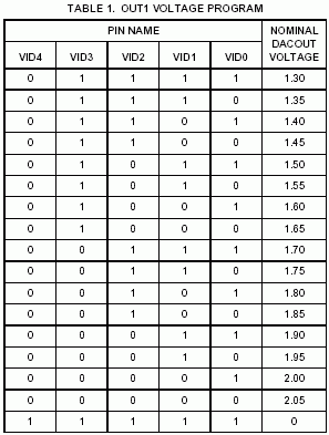
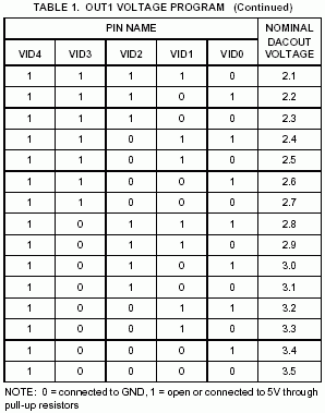
As you can see it supports core voltages of 1.3v to 3.5v.
Note: the one listed as all 1's with the voltage of 0
does just that. It has an output of 0 volts.
Here is a pin-out image of the HIP6021 DC/DC Converter.
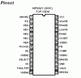
Just your standard 28pin SOIC.
Ok Im going to give some examples of two mods... 1.65v and 1.75v.. from
these I would expect you to get the idea and figure out how to set other
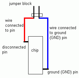
voltages. I would recomend disconnecting all the "VIDx" pins (pins 3-7)
from the motherboard and connecting them to wires with a jumpering design
at the end of the wire then a connection to ground.. that way to quickly
set 0 you would just pop on a jumper and to set 1 you would just remove
the jumper. It would look sort of something like this...
Heres what 1.65v would look like.
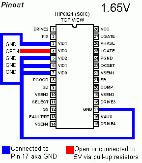
As you can see Pin 4/VID3 is open (1) while Pins 3,5,6,7/VID4,2,1,0 are
connected to Pin 17/GND (Ground) making them a closed (0).
Heres what 1.75v would look like.
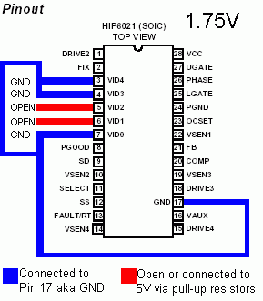
As you can see Pins 5,6/VID2,1 are open (1) while Pins 3,4,7/VID4,3,0 are
connected to Pin 17/GND (Ground) making them a closed (0).
NOTES:: ALWAYS make sure the computer IS OFF before
changing the core voltage. NOT doing so MAY toggle the PGOOD signal and
trigger the over-voltage protection causing the machine to turn off.
Wrote up at: 03:35 AM EST - Revision 0
Wrote up on: Tuesday, November 26, 2002 - Revision 0
Wrote by: Enigma Deadsouls
Website: http://www.oocities.org/enigmadeadsouls
Names/Info from people who have emailed me their test results:
None at this time.
You are free to mirror this page as long as you give me credit and do not change
any of the info unless you ask me first... however youre free to change text
font,size,color background color/image to match youre site. Youre also free to
remove my navigation bar at the bottom of this page as Im sure it would be
pointless on your site... in other words Im ok with changes as long as its not
to the info unless otherwise aproved by me. Also if you mirror it email me and
give me a link and Ill link to it here.