![[guestbook]](../gif/en.o_guest.gif)
This page discusses images and videos of spacecraft and airplane transits over the Sun or Moon, with techniques for airplane identification and ranging. Sequel to discussions on the VVS and Urania message boards. Still work-in-process. | 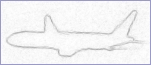
|
 Abstract and Introduction
This page begins with a webography of ISS (International Space Station) transits.
The remainder deals with airplane transits; first, there is a small webography chapter:
[This chapter is roughly okay; a few links may be added or deleted.]
- images of various airplane transits over the Moon or Sun,
- personal websites of airplane spotters,
- airplane spotting resources on the web,
- ephemeris resources on the web.
The next chapters discuss the various airplane transit images in detail.
[At present, there are the janssens and dodi chapters in incomplete draft form. Chapters will be completed and added as the analyses progress.]
The final chapters document the theory of decision, coordinate transforms and model fitting in detail.
[The analysis is, I think, consistent with customary flight dynamics conventions, reasonably complete, and thus fairly close to its final form. Corrections and additions may still be made as a consequence of further spreadsheet modeling and experiences.]
[There still is a final section with reference links. Will be reviewed and integrated in first chapter as relevant.]
Webography of ISS transits
- Excellent website on ISS Sun and Moon transits: iss-transit.sourceforge.net
- CalSKY calculator for ISS passes and transits: www.calsky.com/cs.cgi/Satellites/4?
- Ed's ISS Transits Page (Ed Morana): pictures.ed-morana.com/ISSTransits/
With several ISS lunar and solar transit video's by Ed Morana. - ISS Transits (John Locker): mysite.wanadoo-members.co.uk/satcom_transits
With several ISS lunar and solar transit video's by John Locker.
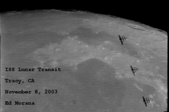
- ISS lunar transit: www.spaceweather.com/eclipses/08nov03d/Morana1.jpg
Image by Ed Morana, 2003-Nov-08. - ISS solar transit: www.wonderplanets.de/iss-transit.html
Webcam video by Torsten Edelmann, 2003-Jun-10. - ISS solar transit: iss-transit.sourceforge.net/subscribers/RolandStalder.html
High-speed video by Roland Stalder, 2003-Aug-16. - ISS transiting Venus while Venus transits the Sun: iss-transit.sourceforge.net/IssVenusTransit.html
An absolutely unique video by Tomá Maruka, 2004-Jun-08. - ISS and STS-114 Discovery solar transit: www.aaw-darmstadt.de/sts-114.htm
Animation and two-frame animated gif, taken from Darmstadt (Germany), 2005-Jul-28.
Webography of airplane transits
Airplane transit images
- users.skynet.be/Luc.Janssens/astronomy_1.html
Video of (DC10/MD10, MD11, or Lockheed L1011 tristar) by Luc Janssens from Veltem-Beisem (Belgium), N50°56.02' E4°37.46', 2003-Jul-18 at 04:05 UT. - users.skynet.be/airwim/welcomephoto21.jpg
Image of Boeing 757-200 (likely) by Wim Van Der Veken from Putte (Belgium), 2005-Jul-20 at 20:43:58 UT. - www.astronomie.be/dodi/birdy2.jpg
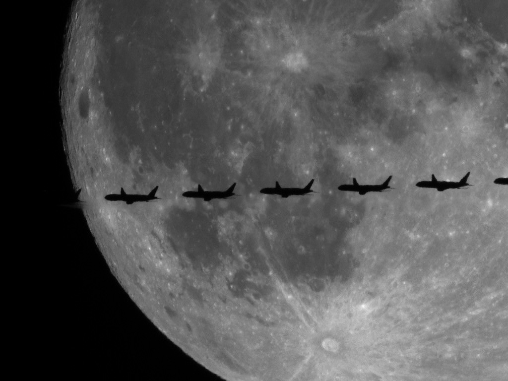
Image of Boeing 777-200 (likely) by Dominique Dierick from Gent (Belgium), N51°02'30" E03°42'24", 2005-Jul-20 at 22:27 UT. - www.airliners.net/open.file/888011/M/
Image of Boeing 757-256 by Javier Guerrero from Madrid (Spain), 2005-Jul-20 at ??:?? UT.
- pmo.2006-Mar-15.jpg
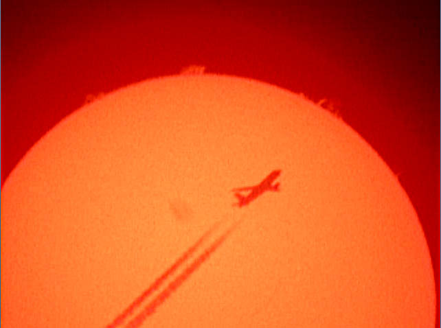
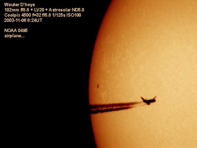
Image of [airplane TBD] by Philippe Mollet from Grimbergen (Belgium), 2006-Mar-15 at ??:?? UT, taken with 40 mm Coronado PST in H-alpha. - wdh.2003-Nov-06.jpg
Image of [airplane TBD] by Wouter D'hoye from ??, 2003-Nov-06 at 08:24 UT.
Personal websites of airplane spotters
- Van Der Veken, Wim: users.skynet.be/airwim/
Airplane spotting resources
Below is a shortlist of sites that I used to find characteristics and dimensions of various airplane types. For many more resources, see the links page of Wim's website: users.skynet.be/airwim/links.htm
- Plane-spotter: www.plane-spotter.com
- Jetphotos: www.jetphotos.net
- Airliners.net: www.airliners.net
- Aircraft-info.net: www.aircraft-info.net
- The Virtual Aviation Museum: www.luftfahrtmuseum.com
- Commercial Aircraft technical data: www.oocities.org/CapeCanaveral/Lab/8803/ftechnic.htm
Ephemeris resources
These resources are useful to find the position of the Moon (and Sun) at any time from any location. The first resource, Astro Viewer, is handy and more than adequate for prediction and preparation of airplane transit imaging.
- Astro Viewer: www.astroviewer.com
Very handy online planisphere. Java applet. - Your Sky (John Walker, Fourmilab): www.fourmilab.ch/yoursky/
Another online planisphere; also featuring horizon views and virtual telescope views. Though less handy than Astro Viewer. - NASA/JPL ephemeris calculator: ssd.jpl.nasa.gov/?ephemerides
The ultimate precision in ephemerides. - IMCCE ephemeris calculator: www.imcce.fr/page.php?nav=fr/ephemerides/formulaire/form_ephepos.php
Roughly equivalent to NASA/JPL.
The Luc Janssens video
Circumstances of imaging
- Images: see users.skynet.be/Luc.Janssens/astronomy_1.html
- Time: 2003-Jul-18 at 04:05 UT
- Location: N50°56.02' E4°37.46' (Veltem-Beisem, Belgium)
- Equipment: amateur telescope (eyepiece projection) plus videocamera
Airplane identification
The video shows three contrails, both at airplane entry over the Moon's rim and at exit. This reduces the alternatives to airplanes with three jet engines, of which two wing-mounted and one tail-mounted:
- Lockheed L-1011 TriStar 1/50/100/150/200/250: www.airliners.net/info/stats.main?id=271
- Lockheed L-1011 TriStar 500: www.airliners.net/info/stats.main?id=272
- McDonnell Douglas DC-10 & Boeing MD-10: www.airliners.net/info/stats.main?id=279
- McDonnell Douglas MD-11: www.airliners.net/info/stats.main?id=112
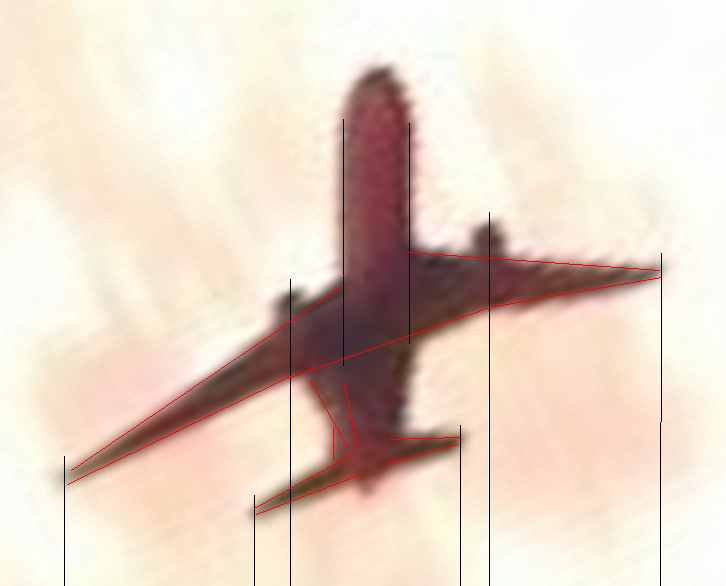
An image from the video is taken, processed (x8 resampled, rotated 26° ccw, cropped), and annotated with lines highlighting the characteristics. See silhouette image 16-1.crop.x8r.lin.png
As discriminating features, note in particular:
- ratio of distance between wing engines to main wing span,
(0.33 for DC-10 and MD-11; 0.45 for L-1011; 0.33 for silhouette) - ratio of rear wing span to main wing span,
(0.33 for DC-10 and MD-11; 0.46 for L-1011; 0.34 for silhouette) - height and form of the tail engine outlet
(inline with engine, above fuselage, for DC-10 and MD-11; lowered for L-1011; distinctly seen higher than fuselage on silhouette)
Obviously, the silhouette does not match the Tristar L-1011 (hence this hypothesis must be rejected), and closely matches both DC-10 and MD-11. The latter types are very similar; the silhouette does not allow to discriminate between these alternatives.
Airplane attitude, distance, flight direction, speed
[Section to be elaborated. Moon is just beyond South, at elevation of some 30° (from ephem). Horizon can roughly be estimated from Moon terminator -> silhouette is tilted some 25°. Airplane flight direction is roughly towards observer, with view from below, and likely in takeoff, i.e. with nonzero pitch. Modelling difficulty: tail top is not seen, i.e. application of the theoretical model below isn't simple. In this case, wing bending isn't important, and the parameters to be estimated are roll/pitch/yaw. Scale can be estimated from comparing silhouette size vs. Moon diameter of roughly 30 arcmin.]
The dodi image
Circumstances of imaging
- Image taken by dodi, see [R.1] or [L.1]
- Time (local): 2005-Jul-21 at 00h27 CEST
(Same, UT): 2005-Jul-20 at 22h27 UT - Location (Ghent):
- 51°02'30" = 51.0417 N
- 03°42'24" = 03.7067 E
- unspecified height (0 m used)
- Telescope (TMB) focal length 651 mm
- CCD pixel size = 5.6 micron
- Time interval between individual plane positions on image: 0.333 sec
- (Reported by gvdb:) List of airplanes arrived at BRU within one hour after image time: one Fokker F27, one Airbus A300, one Boeing B737-300
- [email gvdb]
Ephemerides
[To be added]
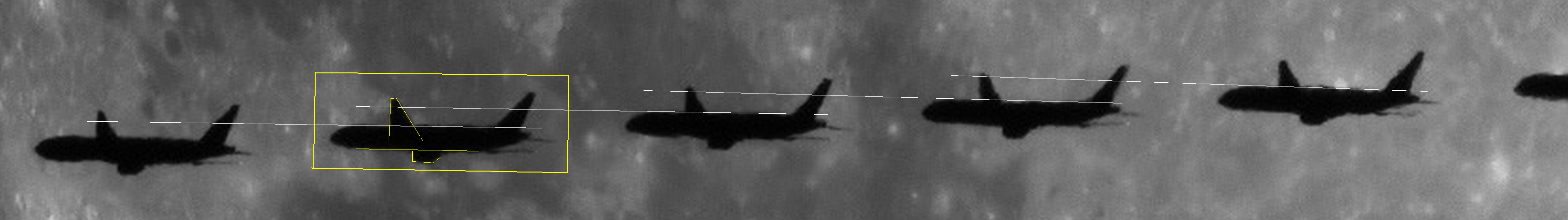
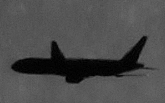
Visible features, see [R.1] or [L.1]
- Fuselage.
- Tail. Note in particular the points where the tail is fixed to the fuselage.
- Left wing. Its high position suggests some clockwise roll of the plane. The angle that the wing makes with the fuselage (nearly perpendicular in projection) suggests quite some yaw: airplane flight is not tangential but has a significant radial component, away from the observer.
- (Left motor: not visible)
- (Left tail wing: not visible)
- Right wing. It is seen roughly at the same height as the bottom side of the fuselage and extends quite far backward, consistent with yaw.
- Right motor. Extends fairly far below the fuselage.
- Right tail wing.
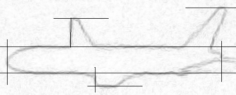
Image processing steps
On the original image ([R.1], [L.1]; for references see bottom of page), each airplane silhouette measures no more than about a hundred pixels, subtends no more than three arcminutes, and suffers from atmospheric seeing effects. [Add description of processing steps: x4 resample and stack, edge detection and rotation to horizontal.]
Data reduction
[To be added]
Theory: the fitting and decision process
Transit images tend to show only a "silhouette" of the airplane, with little detail. Moreover, especially images from large distance (several tens of kilometers) may suffer from small image scale (sometimes no more than a hundred pixels nose-to-tail) and from atmospheric distortions, that make identification difficult.
This chapter describes the various steps of the fitting and decision process, that combines identification of the airplane plus best-fit determination of various unknowns.
Data collection
- Circumstances of imaging.
- Ephemeris calculation, for position of Moon.
- Technical characteristics of various airplane types, from web search.
- Where needed, airplane dimensions are obtained from data reduction on drawings and images.
Image processing
The image is processed and enhanced in order to allow best possible data reduction.
Data reduction
Characteristic features and dimensions are measured on the enhanced image silhouette. Also the tolerances (on imaging and data reduction) are estimated.
Hypothesis and model fitting
- Hypothesis: the airplane to be identified is type "xyz", with characteristic features and dimensions obtained from the data collection step.
- Pre-screening: when it is obvious that one or more model features cannot be matched with the actual silhouette, the hypothesis can be rejected without further analysis.
- Coordinate transforms on the model result in a "model silhouette", as would be seen from the observer location.
- The parameters of these coordinate transforms are fitted such that specific characteristics of the model silhouette match the corresponding characteristics of the actual silhouette as closely as possible. The parameters to be estimated are:
- Wing bending;
- Airplane attitude: roll, pitch, yaw;
- Tilt angle of the CCD camera;
- Scale.
- Examination of the residual differences between the best-fit model silhouette and the actual silhouette.
- Decision whether the hypothesis is acceptable or should be rejected due to residual differences larger than the imaging and data-reduction tolerances on the actual silhouette.
Note that the outcome of this exercise is not (and cannot be) an absolute-certainty identification. The outcome is that specific hypotheses are "possible" (fully fitting with the actual silhouette within tolerances), "marginally possible" (roughly fitting but at the edge of tolerances), or "impossible" (absolutely incompatible).
Ranging and other estimates
The direction of the airplane relative to the observer is already unambiguous from Moon ephemerides. If an acceptable hypothesis is found for the airplane type (one or several), the best-fit parameters allow to calculate various other estimates as well, such as range (distance from observer), flight height, flight direction.
Theory: coordinate transforms on the models under investigation
Introductory remark: the web is rather confusing on attitude and sign conventions. Here the conventions from the article ![[e]](../gif/lc_e.gif) Fighting Dynamics are followed. Also see the wikipedia articles Tait-Bryan (aka Cardan or nautical) angles and Flight dynamics. The image in the latter article clearly shows the meaning of roll, pitch and yaw.
Fighting Dynamics are followed. Also see the wikipedia articles Tait-Bryan (aka Cardan or nautical) angles and Flight dynamics. The image in the latter article clearly shows the meaning of roll, pitch and yaw.
The orthogonal right-handed (x,y,z) coordinate system
- origin at the airplane's position,
- x-axis horizontal and pointing away from the observer,
- y-axis horizontal and pointing to the right as seen by the observer,
- z-axis vertical and pointing downward.
For our analysis, this coordinate system moves along with the airplane in translation, but is kept fixed in orientation relative to the Earth and to the observer. The transforms below define the airplane model's attitude and the coordinates of the various points relative to this coordinate system.
Initial placement of the airplane model
The airplane model is initially placed such that it is flying horizontally and straight away from the observer, i.e. with zero roll, pitch and yaw angles relative to the (x,y,z) coordinate system:
- fuselage center axis coinciding with the x-axis,
- fuselage rear at x=0,
- fuselage nose at positive x.
The various points of the airplane model have initial coordinates (x0,y0,z0) that are obtained from specifications and from measurements on drawings.
Note: for reasons of scale normalization, the coordinates are expressed in "mul", a unit that stands for "milli-unit-length", or one-thousandth part of the nose-to-rear length of the airplane's fuselage.
First coordinate transform: wing bending
In-flight, when the airplane is carried aloft by the wings, the wings bend upward as compared to the on-ground situation, when the wings hang at the fuselage. Every point (x0,y0,z0) of the model is transformed to new coordinates (x1,y1,z1), that are actually the same as the original ones for most points, except for those on the wings. The transform for these wing points is modeled as a cylindrical bending along the length of the wing, such that the wing length remains unchanged.
With:
- all lengths, angles and displacements hereunder measured in projection on the yz plane (i.e. in front view),
- wl (airplane constant): length of each wing, from fuselage to wingtip,
- ψ (airplane constant): inclination angle of the unbended wing (on-ground) relative to horizontal,
- φ (unknown optimization parameter for fitting the model with silhouette): angle between unbended wing and the chord from fuselage to wingtip of the bended wing,
- wa: "up" displacement of wingtip, perpendicular to the original unbended wing,
- wb: "inward" displacement of wingtip, parallel to the original unbended wing,
- δz: vertical displacement of wingtip,
- δy: horizontal displacement of wingtip,
and with small-angle expansions for cos and sin:
- cos(φ) = 1 - (φ2)/2
- sin(φ) = φ - (φ3)/6
we obtain:
- wa = wl · φ
- wb = (2/3) · wl · φ2
- δz = wa cos(ψ) - wb sin(ψ)
- δy = wa sin(ψ) + wb cos(ψ)
These δz and δy are the wingtip-coordinate corrections from (y0,z0) to (y1,z1) in absolute value, and must be applied with the appropriate signs for the left and right wings.
Second coordinate transform: roll
The airplane model is rotated about the x-axis over the roll angle γ, with positive roll corresponding to clockwise rotation. Every point (x1,y1,z1) of the model is rotated to new coordinates (x2,y2,z2):
- x2 = x1
- y2 = y1 cos(γ) - z1 sin(γ)
- z2 = y1 sin(γ) + z1 cos(γ)
Third coordinate transform: pitch
The airplane model is rotated about the y-axis over the pitch angle β, with positive pitch corresponding to clockwise rotation (i.e. nose upward). Every point (x2,y2,z2) of the model is rotated to new coordinates (x3,y3,z3):
- x3 = x2 cos(β) + z2 sin(β)
- y3 = y2
- z3 = -x2 sin(β) + z2 cos(β)
Fourth coordinate transform: yaw
The airplane model is rotated about the z-axis over the yaw angle α, with positive yaw corresponding to clockwise rotation (i.e. to the right). Every point (x3,y3,z3) of the model is rotated to new coordinates (x4,y4,z4):
- x4 = x3 cos(α) - y3 sin(α)
- y4 = x3 sin(α) + y3 cos(α)
- z4 = z3
Fifth coordinate transform: line-of-sight elevation angle
The observer is looking from below towards the airplane at elevation angle el. This can be modeled, alternatively, by rotating every point (x4,y4,z4) of the model about the y-axis over the elevation angle el to new coordinates (x5,y5,z5):
- x5 = x4 cos(el) - z4 sin(el)
- y5 = y4
- z5 = x4 sin(el) + z4 cos(el)
Sixth coordinate transform: tilt
The two-dimensional silhouette of the model is now in the (y,z) plane. This silhouette is rotated over tilt angle θ, measured positive clockwise. Every point (y5,z5) of the model silhouette is rotated to new coordinates (y6,z6):
- y6 = y5 cos(θ) - z5 sin(θ)
- z6 = y5 sin(θ) + z5 cos(θ)
Seventh coordinate transform: scale
The two-dimensional silhouette of the model is scaled by a multiplier M. Every point (y6,z6) of the model is scaled to new coordinates (y7,z7):
- y7 = M · y6
- z7 = M · z6
Theory: fitting the model to the image silhouette
Comment on wing bending
Wing bending, even though a small effect, should be duly estimated in order to avoid errors in the estimation of roll. For the purposes of model fitting, we consider the wing bending angle as an independent free variable, even though it is not quite free in reality. It is determined by lift forces on the wings and by wing stiffness, i.e. by airplane design and construction, but unknown for us (since not publicly documented by manufacturers).
Comment on roll
Obviously, the roll angle is an independent free variable for model fitting.
Comment on yaw
Obviously, the yaw angle is an independent free variable for model fitting.
Yaw, as defined above, is positive (between 0 and 180°) for airplanes flying to the right, and negative (between 0 and -180°) for airplanes flying to the left. In absolute value, yaw is 90° for airplanes flying perpendicular to the observer's direction, and smaller [resp. larger] than 90° for airplanes flying away from [resp. closer towards] the observer.
Note that the airplane's flight direction, measured as an angle from North over East, is the sum of yaw plus the line-of-sight azimuth angle, also measured from North over East.
Comment on tilt and pitch
In general, the image silhouette is not horizontal, but more or less tilted relative to the sides of the camera chip. This tilt is due to three causes:
- unknown tilt, relative to horizontal, of the camera itself,
- the visual effect of unknown yaw in combination with a view from below the airplane: the nose of an airplane flying away from [resp. approaching] the observer is seen lower [resp. higher] than its rear end,
- unknown pitch of the airplane.
Instead of estimating these three effects separately, we null them out by:
- rotating the actual image silhouette such as to make it horizontal, i.e. such that the fuselage center axis coincides with the y-axis,
- assuming that the airplane itself is flying at an a-priori pitch estimated somewhat arbitrarily (usually zero, since airplanes fly at nominally zero pitch most of the time)(this fixes the pitch angle for the third transform as per above),
- rotating the model silhouette such as to make it horizontal as well (the tilt angle θ, for the sixth transform as per above, is calculated accordingly).
Following this nulling procedure, any difference between estimated and real pitch of the airplane would not introduce any errors in model fitting for the purposes of airplane recognition, though it may lead to a small error on the estimation for yaw.
Characteristics derived from the actual image silhouette
We assume that both left and right wingtips are sufficiently well visible on the silhouette. From that silhouette (in the y,z plane), rotated with the fuselage in horizontal position, we estimate:
- hl: height of the left wingtip,
- hr: height of the right wingtip,
- ht: height of the tail,
- τ: the angle, in projection, between the fuselage axis and the line connecting the wingtips (or, to be precise, the line connecting the rear ends of the wingtips),
with all heights measured relative to the center axis of the fuselage. From these we derive:
- rasum = (hl+hr)/ht
- radif = (hl-hr)/ht
- τ (same as above)
These three characteristics of the silhouette (as two ratio's and one angle) are "dimensionless" and independent of scale.
Remark: it is assumed above that the rear ends of the wingtips can be located on the silhouette with little tolerance. If this is not the case, some other angle may be used instead, such as for instance the angle between the fuselage axis and the front side of one of the wings.
Model fitting
In line with the characteristics (rasum,radif,τ) of the actual image silhouette, the corresponding characteristics (rasum',radif',τ') can be calculated on the transformed model. Evidently, these primed characteristics are function of the transform parameters:
- wing bending angle φ (independent free variable for model-fitting),
- roll angle γ (independent free variable for model-fitting),
- pitch angle β (estimated as a constant, usually zero),
- yaw angle α (independent free variable for model-fitting),
- line-of-sight altitude angle alt (known exactly from Moon ephemerides),
- tilt angle θ (calculated to null out image tilt and residual pitch).
We are thus left with three independent free variables (φ,γ,α) that can be tuned by successive approximation until the three model characteristics exactly equal the three independent image silhouette characteristics. In other words, we tune (φ,γ,α) such that (rasum',radif',τ') = (rasum,radif,τ).
The successive-approximation convergence is reasonably fast since average wingtip lift (rasum) is predominantly determined by wing bending (φ), apparent height difference between left and right wings (radif) is predominantly determined by roll (γ), and apparent wing-to-fuselage angle (τ) is predominantly determined by yaw (α).
This method of best-fitting the model to the actual silhouette is fully scale-independent. Note that none of these matched (rasum,radif,τ) parameters can be used anymore to discriminate between various airplane models - because they are exactly matched for whichever model! Otherwise said, in order to assess the acceptability of the hypothesis, other values must be compared between the transformed model and the actual silhouette.
Scaling
[Section to be completed]
Reference links (subject to review)
To other sites
- [R.1] Original image: www.astronomie.be/dodi/birdy2.jpg
- [R.2] JPL ephemeris calculator: ssd.jpl.nasa.gov/?ephemerides
- [R.3] IMCCE ephemeris calculator: www.imcce.fr/page.php?nav=fr/ephemerides/formulaire/form_ephepos.php
- [R.4] European Air Transport (i.e. DHL) fleet: www.planespotters.net/Airline/European_Air_Transport
- [R.5] Commercial Aircraft technical data: www.oocities.org/CapeCanaveral/Lab/8803/ftechnic.htm
- B757, A300: www.oocities.org/CapeCanaveral/Lab/8803/tech_wb.htm#2main
Note: A300 diameter may be wrong here, other sources say xxx
- B757, A300: www.oocities.org/CapeCanaveral/Lab/8803/tech_wb.htm#2main
- [R.6] Virtual Aviation Museum: www.luftfahrtmuseum.com/htmi/itk/p6.htm
- [R.7] PanAm's Aircraft, Airbus A300B4: www.panamair.org/OLDSITE/Aircraft/airbusa300.htm
- [R.x] Roll, pitch, yaw: www.nasm.si.edu/exhibitions/gal109/NEWHTF/HTF541B.HTM
To local files
- [L.1] dodi image (local copy of [R.1]): birdy2.jpg
- [L.2] Cut-out strip: strip4.3.png
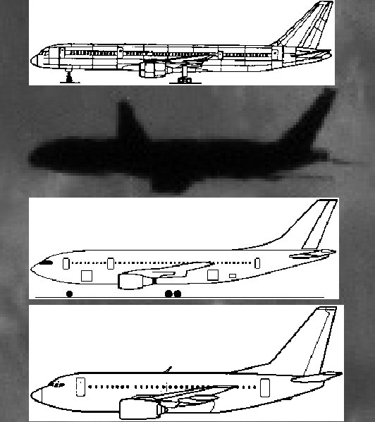
- [L.3] Profile with B757-200, A300-600, B737-300: planes.jpg
- [L.4] Stacked by bdc: Vliegtuig_Som.jpg
- [L.5] After edge-detection: vliegtuig_som.3.png
- Drawings from [R.6]
- [L.6.1] B757-200: r6.b757-200.gif
- [L.6.2] B737-300: r6.b737-300.gif
- [L.6.3] A300-600: r6.a300-600.gif
- Drawing from [R.7]
- [L.7] A300B4: r7.a300-b4.jpg