IMPEDANCE
COMPENSATION CIRCUITS
0. Introduction
Often an available amplifier is more
comfortable with flat-impedance loads. In reality a
loudspeaker has a complex impedance. To compensate
for this, circuits can be designed and implemented.
Probably the most common impedance compensation
circuit is the so-called Zobel network, which has
many variations of itself the simplest being the
capacitor-resistor network. The full Zobel network
would also compensate for the resonance impedance
peak of the driver at the resonant frequency, Fs.
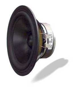
1. Woofer
One of the most famous drivers in the
DIY world is the Vifa P17WJ-00-08. Many builders use
it because it has a smooth frequency response and
resonable bandwidth. Because many constructors use it,
the said driver was chosen to be modeled in this
website. The following is a picture of the the driver
unit along with its Thiele-Small Parameters.
Thiele-Small Parameters
|
| Revc |
|
5.8 ohms
|
|
DC resistance of voice coil |
| Levc |
|
0.55 mH |
|
voice coil inductance |
| Bl |
|
6.5 T.m |
|
force factor |
| Qts |
|
0.35 |
|
total Q
|
| Qes |
|
0.45 |
|
electrical Q |
| Qms |
|
1.55 |
|
mechanical Q |
| Fs |
|
37 Hz |
|
resonant frequency |
| Mmd |
|
0.014 kg |
|
mass of cone + voice coil +
etc.
|
| Rms |
|
2.08 |
|
resistance of suspension |
| Cms |
|
1.34 mm/N |
|
compliance of suspension |
| Sd |
|
0.0136 sq.m |
|
effective cone area |
| Vas |
|
0.0347 cu.m |
|
equivalent acoustic volume |
| Xmax |
|
0.004 m |
|
linear travel of voice coil |
| FR |
|
37 - 5000kHz |
|
frequency response |
| Vd |
|
0.0005 cu.m |
|
driver unit volume displacement |
The driver can be modelled with the
following electroacoustic circuit.
Some of the circuit values above are
already obvious. Veg represents the amplifier and is
assumed to have no output resistance. The remaining
values were calculated from,
Cmes = Mmd/(Bl*Bl) = electrical
analog of driver mechanical cone mass
Lces = Cmd*Bl*Bl = electrical analog of driver
mechanical suspension compliance
Res = Bl*Bl/Rmd = electrical analog of driver
mechanical suspension resistance
Cmef = 8*po*Ad*Ad*Ad/(3*Bl*Bl) = electrical analog of
air load on the driver unit's cone
where:
po = air density = 1.18 kg/cu.m
Ad = effective radius of the driver unit's cone
The following is a screenshot of the
driver unit's impedance curve.
Some Thiele-Small Parameters can be
calculated from the impedance curve above. Using
equations from [1], we get,
Fs = 35.604 Hz
Fl = 19.121 Hz
Fh = 65.615 Hz
Ro = Rmax/Revc = 4.51 ohms
Rx = Revc*sqrt(Ro) = 12.32
Qms = Fs*sqrt(Ro)/(Fh-Fl) = 1.63
Qes = Qms/(Ro-1) = 0.463
Qts = Qms/Ro = 0.361
The calculated parameters are close
enough and one would get near-real-world parameters
with real-world impedance curves.
It is obvious that the amplifier
would be more happy if the effective impedance
accross the speaker terminals were flat. It is
possible to flatten the raw impedance curve of a
driver unit by using impedance compensation circuits.
With impedance compensation circuits, the driver unit
equivalent circuit model looks like
The RC circuit formed by Ric and Cic
helps to flatten the rising impedance due to the
voice coil and on the other hand the LCR circuit
formed by Lic1, Cic1 and Ric1 flattens the impedance
peak due to Eddy currents, back emf and so on (at the
driver unit's resonant frequency). The circuit values
can be calculated from,
Ric = Revc (for a flat impedance
curve) or 1.26Revc (which is better for the amplifier)
Cic = Levc/(Revc*Revc)
Lic1 = Revc*Qes/(2*pi*Fs)
Cic1 = 1/(2*pi*Fs*Revc*Qes)
Ric1 = Revc + (Revc*Qes)/Qms
The voice coil is basically an RL
circuit, therefore the impedance accross the voice
coil is directly proportional with frequency. An RC
circuit exibits a decreasing impedance with frequency.
Placing such a circuit in parallel with the voice
coil would help to counteract the rising impedance.
The following picture shows the effect of the RC
circuit.
The RC circuit has successfully
compensated for the rising impedance of the voic coil.
The lowest impedance is 5.45 ohms and at 10kHz, the
impedance is now 5.8 ohms instead of 35 ohms.
What remains to be adjusted is the
peak impedance at resonance. Ignoring the effects of
the other circuit components, Lces and Cmes are
essentially open-circuit at resonance, which explains
the peak impedance of 26.2 ohms. A series LCR circuit
is basically equal to R at the resonant frequency of
L and C. Designing such a circuit to resonate at Fs
would basically result in the following impedance (at
resonance),
Z = (Ric1*(Revc + Res))/(Ric1 + Revc
+ Res) = 5.82 ohms
which is almost equal to the DC
resistance of the voice coil. This is neglecting the
(small) effects of Levc, Cmef, Ric and Cic. The
following picture shows the effect of Lic1, Cic1 and
Ric1 circuit in place.
The combined effects of the above-mentioned
RC and LCR circuits results in the following
impedance curve.
The green curve shows a closer look
at the red curve. As you can see, the voice coil
impedance is now resonably flat. The peak impedance
is equal to 5.89 ohms and the trough corresponds to
an impedance of 5.3 ohms, which when subtracted from
the former yields an impedance difference of 0.59
ohms.
More complex impedance compensation
circuits can give a more flat impedance curve, but
final building cost would be higher.
|