0. Introduction
The equations in this paper were derived mainly
because the author has been kown to ask the question,
"How was this equation derived?" In his
time as a curious boy, not one toy was spared from
being disected and reverse-engineered. On the other
hand...
In the case of vented-box loudspeakers, ports are
used to extend its low-frequency extension by using
the energy at the rear side of the driver unit's cone.
In the case of bandpass enclosures, ports are used to
limit the passband of the loudspeaker system. Vented
systems are known for being sensitive to design and
construction errors or misalignments. The driver's
Thiele-Small parameters should be as accurate as
possible so that equations and CAD software can yield
results that are most relevant to the driver and
design parameters. We want to further reduce the
chance of misalignment by carefully building the
enclosure, but the question of port diameter and port
length now arises.
As well as being a function of enclosure volume
and vent radius, port length is also dependent on the
speed of sound. Several books and Internet sites
quote equations for port diameter and vent length,
but nearly all of these equations assume the speed of
sound to be 344m/s. It will be shown that the actual
speed of sound is a significant factor in calculating
the required port length. Although the effects on the
enclosure's resonant frequency may be insignificant,
the exact port length would be helpful in calculating
enclosure dimensions. More so when enclosure size is
critical.
It is often the case of the vent(s) being too long
to fit in the accompanying enclosure. The builder has
to reduce the port radius so that port length is
consequently reduced, but in doing so the problem of
port noise arises. Introducing flares to the port can
significantly reduce port noise while still having
practical port dimensions. However, the author has
yet to see an equation for calculating the dimensions
of flared vents. In this paper, an equation is
presented that can be used to approximate the
dimensions of flared ports.
1. Cylindrical Vents
In mechanical terms, a vented-box is simply a
spring-mass resonant system. The air in the box acts
as a spring and has a stiffness that is directly
proportional to the port's area. On the other hand,
the lump of air in the port acts as a lump of mass.
The box resonant frequency can be calculated from the
following equation.

where:
Fb - box resonant frequency (Hz)
Cmb - box compliance (m/N)
Mmp - port mass (kg)
pi = 3.1415926535897932384626433832795...
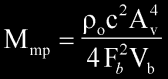
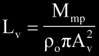
Cmb can be calculated from,
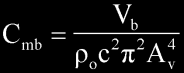
where:
Vb - net box volume (cubic meters)
po - density of air (kg / cubic meters)
c - speed of sound (m/s)
Av - port radius (m)
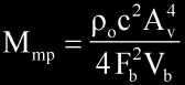
From the equation of Fb, we have the equation for Mmp
(as a function of Cmb and Fb),
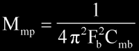
or
The speed of sound can be calculated from,
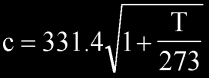
where T is the ambient temperatur in Celsius degrees.
Now, the volume of air, Vp, in the cylindrical port can
be calculated from the following equation.
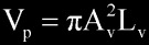
where Lv is the port length in meters. Since mass is
equal to volume multiplied by density, the lump of mass
in the port can be calculated from,

Manipulating this equation for Lv,
and since
Lv
simplifies to,

However, both ends of the cylindrical tube are
actually loaded with a small mass of air. According to
Beranek, the flanged end of a tube actually "extends"
by 0.85*Av whereas the free end of the tube extends by 0.613*Av.
Usually, the port is mounted flush against the
loudspeaker baffle while the other end of the port is
left unflanged, therefore the corrected equation for Lv
is,

2. Multiple Cylindrical Vents
With high-power driver units, port noise can be an
audible problem. A solution is to use a port with a
larger vent radius. Alternatively, the builder may elect
to use two or more vents when a single large vent is not
readily-available or impractical to build.
From the Loudspeaker Design Cookbook (by Vance
Dickason)
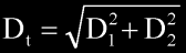
where:
Dt = effective diameter of the combined vents
D1, D2 = individual port diamter
For equi-diameter vents, D1 = D2, and so
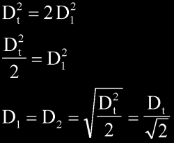
Now D = 2A, so

or in the case of N number of "equiradius"
vents,

where Av is now the effective vent radius. Cmb for
multiple vents is now,

Since all the ports have equal mass, each port will
have mass equal to

Therefore each port length will be

For example, given:
c = 342.2m/s (at 18 degrees Celsius)
N = 2 ports
Av = 0.045m
Fb = 16Hz
Vb = 0.142 cubic meters
Each port length will be Lv = 0.972m (or 38.3inches)
If the ambient temperature happens to be 35 degrees
Celsius (during summer), c increases to 352m/s
Consequently, Lv = 1.03m (or 40.7inches)
When only one vent is used, the change in port length
(due to change in temperature) can be neglected. But when
two or more vents are used, the change in ambient
temperature has a significant change in port length.
3. Flared Vents
-- 22 June, 2002: Please note
that this section of this page needs to be corrected.
Apparently, the equation presented below over estimates
the end-correction, so please disregard this section
until the necessary corrections have been made. I
apologize for any inconvenience this may have caused.
When the calculated port length is too long, given a
particular enclosure size and tuning frequency, the
builder may slightly decrease the vent radius, which will
correspondingly reduce port length. Unfortunately, by
doing so, port noise will almost certainly become a
problem; to rectify the problem flared vents may be used.
First, we derive the equation for the volume of air in
the flare. Pictured below is half of the cross section of
a port's flared end (along with the derivation for the
flare volume).
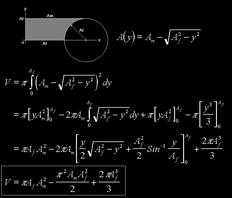
Fig. 1: Derivation of flare volume.
Rotating the shaded area about the y-axis
gives the volume of air in the flare. The flare radius is
a function of y and is given by the equation
A(y) = Am - sqrt(Af*Af - y*y)
where:
Am - mouth radius of the flare and is equal to Af +
At
At - throat radius of the flare
Af - flare radius
When both ends of the cylindrical vent
have flared ends like the one pictured below,
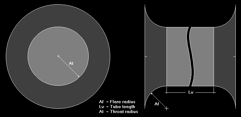
Fig. 2: Cylindrical vent with both ends
flared.
The required tube length, Lt, can be
calculated from
Lt
= N*c*c*At*At / (4*pi*Fb*Fb*Vb) - 0.85*Am - 0.613*Am
- 2*V / (pi*At*At)
and if only one end is flared,
Lt
= N*c*c*At*At / (4*pi*Fb*Fb*Vb) - 0.85*Am - 0.613*At
- V / (pi*At*At)
For example, given both ends are flared and:
c = 352m/s (at 35 degrees Celsius)
N = 1 port
At = 0.045m
Af = 0.0254m (1inch)
Fb = 16Hz
Vb = 0.142 cubic meters
Each port length will be Lv = 0.382m (or 15inches) as
opposed to Lv = 0.483 (or 19inches) when no flares are
used.
Assuming (just assuming) for a moment that air was
incompressible, using the continuity equation for fluids,
At*At*vt = Am*Am*vm
where vt and vm are the fluid velocities at the throat
and mouth respectively, we can calculate the appoximate
exit velocity as
vm = At*At*vt / Am*Am = 7m/s
which translates to a 60% reduction in port velocity (assuming
vt to be 17m/s or 5% the speed of sound). Halfway out the
flare, the air velocity is 15m/s -- 12% down from 17m/s.
In practice, we can expect slightly higher exit
velocities as air is not an ideal fluid.
4. Conclusion
A derivation for the general equation for port
velocity is presented. It was shown that port length is
not only dependent on port radius and net box volume, but
also on the actual speed of sound. The effects on
calculated resonant frequency may be neglected, but the
effects of the change in the speed of sound on the port
length cannot be ignored; especially when using two ore
more ports.
An approximate equation for flared ports was presented.
The presented equation may be used by builders to build
their own flared vents when long cylindrical vents are
impractical or when commercial flared vents are either
too expensive or unavailable.
(corrections?)
|