|
|
| ****** |
|
|
|
|
|
Note:
Apple, Apple Macintosh, MacOS, Märklin, Märklin Digital, Märklin Digital=, Märklin DELTA, Märklin systems, Märklin mfx, Märklin CS, Märklin Central Station, Märklin CS2, MFX, Lenz, Lenz Digital Plus, Roco, Digital is Cool, LokMaus, NMRA, Trix, Selectrix, Selectrix 2000, Rautenhaus Digital, Fleischmann, Fleischmann FMZ, TwinCenter, ZIMO, Wangrow, North Coast Engineering, Digitrax, LocoNet, Motorola, Modeltreno Digital Line, Uhlenbrock Digital, Uhlenbrock Intellibox, ESU LokPilot, ESU LokSound2, ESU LokSound3, ESU mfx, ESU ECoS, Tams, EasyControl, Bachmann, Bachmann Dynamis, GleisReporter, MIBA etc. are copyrighted and registered trademarks of their respective owners.
|
|
|
|
|
SimpleDigitalLocomotive FAQ
|
|
|
|
|
Connecting to CS2 / Verbindung zur CS2 (2008-12-06)
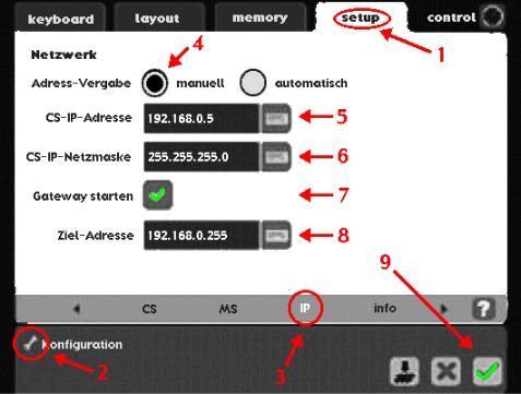
This digital central unit has a built-in Ethernet-port for connecting the Mac to it. Use a crossover-cable to connect the CS2's Ethernet-port with the Ethernet-port of your Mac. Make suitable settings inside the CS2: give the CS2 an IP-address which fits to your setup of a local area-network (LAN), for example "192.168.0.5".
- go to tab "setup" in the CS2,
- click on the wrench-icon (Schraubenschlüssel) in the lower left-corner to enter configuration mode,
- select register-tab "IP",
- select manually setting of the IP-address,
- enter the IP-address which your CS2 should get,
- enter CS-IP-Netmask "255.255.255.0",
- enable "Start gateway" = "Gateway starten" (otherwise the CS2 will not talk via Ethernet, but can still read datagrams),
- enter as destination address the broadcast-address of your LAN (#.#.0.255),
- confirm all settings by clicking on the green icon in the lower right corner of the window.
Make similiar settings on your Mac, using the system preferences "Network". Ensure that both, CS2 and Mac, have different IP-addresses. Example for the Mac's IP-address might be: "192.168.0.1". Mac and CS2 must have their IP-addresses within the same LAN-range.
On the Mac, you must also ensure that the Firewall enables UDP-traffic via Ethernet-port. When using MacOS-X 10.4, make these Firewall-settings within the system preferences "Sharing", tab "Firewall". You can disable the Firewall entirely or you can use "Advanved options" to enable UDP-traffic only.
When using MacOS-X 10.5 or later, make such settings within the system preferences "Security". Again, you can disable there the Firewall entirely or you select your SDL-X application and give it special advanced options, allowing UDP-traffic.
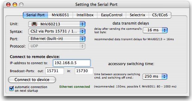
Then launch SDL-X on your Mac and call the window "Setting the Serial Port" (Cmd-I). Here you must select the desired digital central unit. When selecting "Mrkl60213", the program will automatically set the only available syntax and the protocol method "UDP". You must select the Ethernet-port to which your CS2 is connected. Then you must enter the IP-address of the CS2 and the two broadcast-ports for communication: for outgoing datas you must enter the port number "15731" and for incoming datas you must enter the port number "15730". See the following picture. Once this is done, you must push the button "Connect to device". We recommend to set an accessory switching time of 250ms. Accessories with a time less than this defined inside the CS2 itself, should be set off by the CS2 earlier. But SDL-X will send an "accessory-off" command to the CS2 in any case (as long as the connection will stay "on").
In case of performance problems you can disable the usage of the UDP-ports by deactivating the checkboxes at the right side of the port's edit fields. In case the connection is already done (perhaps automatically on startup), then this deactivation will have effect only after a program restart. Deactivating the incoming port 15730 might make sense in case the CS2 is sending too much datas.
More settings to the UDP-traffic handling can be done within the tab "CS/ECoS" of this window.
Which address to be entered for commanding vehicles with a CS2:
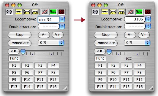
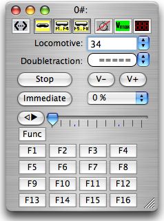
The CS2 will send vehicle commands to the tracks no matter if these vehicles are defined in it's own internal database (concerning old-style decoders with MM or DCC format). Commanding vehicles with a MM1/MM2-decoder can be done by entering the decoder's address in the "ControlF" window of SDL-X:
Commanding vehicles with a DCC-decoder in it can be done by entering the decoder's address prefixed by the word "dcc". SDL-X will then automatically calculate the correct address to command this decoder:
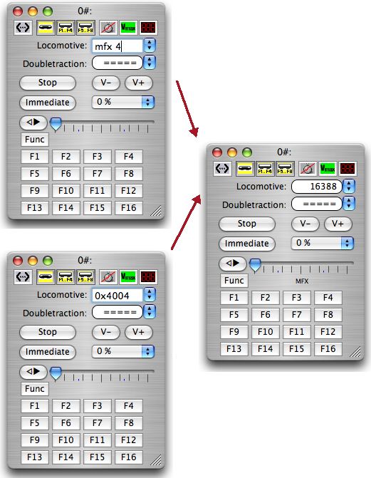
For mfx-decoders this is a little bit more complicated. We believe, that the CS2 will send only commands to the tracks in case of these if they are defined inside the CS2's own vehicle table. To make the CS2 accept such commands, you must know the vehicles "uid". Valid "uid"s of mfx-vehicles starts at 4000hex. You can retrieve the currently valid "uid"s by examining the CS2-backup-file "lokomotive.cs2" (plain ASCII file). SDL-X accepts to ways of entering such "uid"s as addresses: by prefixing the word "mfx" of by entering hex-values (postfixing "h" or prefixing "0x") or a combination of both:
The same address-entering methods can be used in SDL-X's window "Vehicle table", too. When saving the vehicle table to disk, SDL-X will caculate and save the decimal addresses. So when loading the file on next program launch, you will no longer see your prefixes but the correct decimal values. Currently SDL-X offers you to access up to 17 decoder functions, although the CS2 might be capable to command up to 32 functions for each decoder.
Which address to be entered for commanding accessories with a CS2:
The CS2 will accept MM-decoder addresses (range 1 - 320 or perhaps up to 1024). Using the windows "Keyboard" or switchboard windows, you must simply enter the old-style MM-decoder addresses, like being connected to a mrkl6051 or IB.
*
*
Using "GleisReporter" connected to CS1 /
Benutzung des "GleisReporter" bei Anschluß an eine CS1
(2009-01-10)
The "GleisReporter" is a sensor module similiar to a s88-module, but operating on the CAN-Bus. The "GleisReporter" module was invented by Dipl.-Ing. Thorsten Mumm in 2008 and was first described in the magazine "MIBA 12/2008" (link to overview in German: http://www.miba.de/miba/08/12/22.htm).
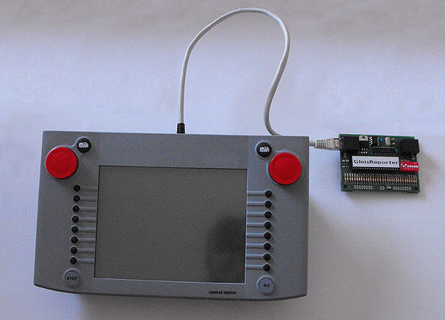
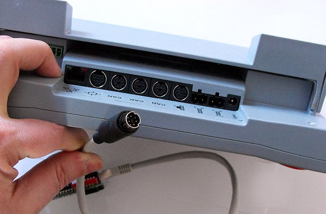
This short report will tell you how to connect such a "GleisReporter" module to the CS1/ECoS and how to use it with SimpleDigitalLocomotive. First you must know is that you need an adapter cable "CAN-Bus to CAT5", because the module itself has two CAT5-connecters (it doesn't matter which one of this two CAT5 connecters will be used).
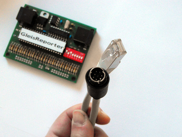
The CAN-plug of this adaptor cable must be pluged into one of the three CAN-plugs of the CS1. You will need no additional adaptor.
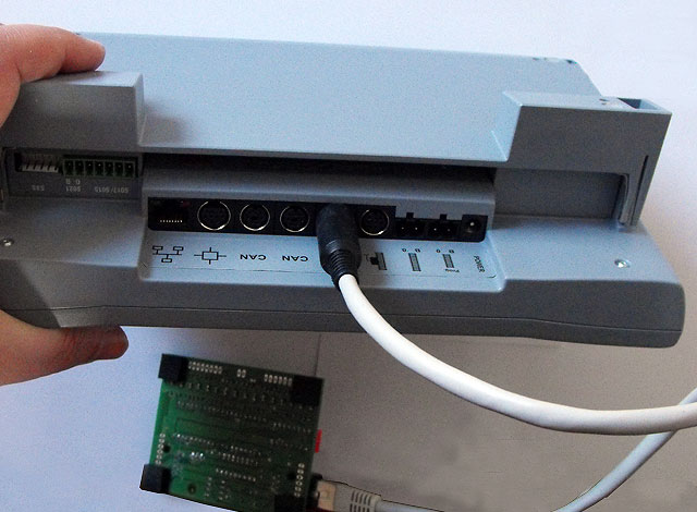
Then plug the CAT5 plug of the adaptor cable into the first "GleisReporter" module.
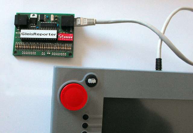
Then you must adjust the dip-switches of the "GleisReporter" module. In the picture above the module is set to address #6 (if counted from 1). Now turn on your CS1. Inside the CS1 you must go to "Settings of the CS1":
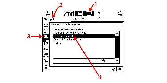
1. select the "Settings" screen,
2. go to "Setup 1",
3. select "Components in system",
4. select "S88-Bus Control" to see the "S88-Bus Control" screen:
In this "S88-Bus Control" screen you must define all the sensor modules connected to your CS1, no matter which bus they are using. You can mix "GleisReporter" modules with S88-modules. In this case you must avoid address collision: the S88-Bus will occupy the first addresses, because you cannot determine their addresses by dip-switches. S88-Bus modules will be addressed automatically without any gap between them. so give the first "GleisReporter" module an address higher than the last available S88-module in your system connected to your CS1/ECoS. In the following example we will have space left for 5 S88-modules, although only one S88-module is connected. The first "GleisReporter" will get address #6 (the CS1-user inetrface counts the sensor modules from #1), so we must have defined in the following window 6 sensor modules as a minimum:
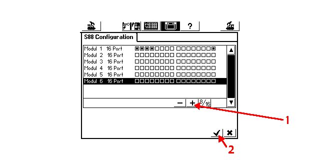
1. click on the "+" button until you have enough modules defined,
2. then click on the checkmark in the lower right corner of the window to save your settings and to leave this window.
3. Click also on the checkmark in the now reappearing settings window to leave "Settings" screen.
Then launch SimpleDigitalLocomotive. Goto "Preferences" window:
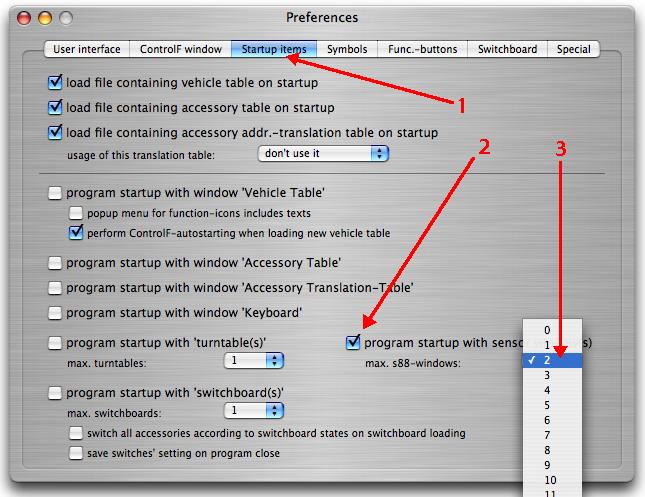
1. select "Startup items",
2. checkbox "program startup with sensor module(s)" must be set,
3. and you must set the desired number of sensor modules.
In our example we want to watch only the first S88-Bus module and the first "GleisReporter" module. So we will need two windows.
In this example we might alternatively set the number to 6, but it is allowed to use any other amount of windows greater than zero, because the CS1 will report sensor events automatically once they are requested by the computer program. SimpleDigitalLocomotive will do this request for every sensor window containing a sensor module number. Gaps are allowed. It this not necessary to create sensor windows for non-existing modules. Please obey: this is only valid in case you are using a CS1/ECoS/Dynamis!
4. Leave "Preferences" window. Settings will have effect on next program relaunch.
Now in our example, with one S88-Bus module and one "GleisReporter" set to address #6, we will define in the already running SimpleDigitalLocomotive application two sensor windows to watch the modules immediately:
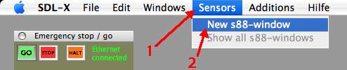
1. menubar item "Sensors",
2. click on the item "New s88-window" twice to see two new sensor windows.
Make the approbiate settings inside the upcoming sensor windows: set the refresh rate always to "no polling". And set their module numbers: the one showing the S88-Bus results of our example must get #1, and the window showing the sensors of the CAN-Bus connected "GleisReporter" with it's dip-switches set to address #6 (counted from 1) must get module number #6:
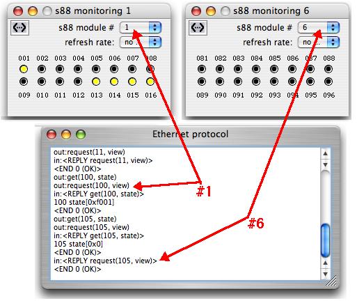
If you turn the "Ethernet protocol" window on, you will see the commands SimpleDigitalLocomotive had sent to the CS1: first requesting state and then view for both open windows. These requests will be renewed if you are changing the sensor window's module number afterwards. Sensor window settings will be saved at program shutdown and will be rebuilded on next program start, if you made the approbiate settings within the window "Preferences", tab "Startup items" as mentioned above.
Threeway-turnout / Dreiwegeweiche (2007-11-18)
The Threeway-Turnout defining inside the Switchboard
In the switchboard you can define also threeway-turnouts. These have 3 states (straight, left, right), which are controlled normally by two solenoids. The state "straight" requires both solenoids to be set to "straight", the state "right" requires the "left" solenoid to be set "straight" and the "right" solenoid to be set "right". For the state "left" the "right" solenoid must be set to "straight" and the "left" one to "left". This requires in analogue operation mode (if there is no additional logic used) 4 buttons (= two pairs of buttons) or in digital mode 4 ports of an accessory-decoder (= two accessory addresses).
Threeway-Turnout defining when using a 6021/6051, IB or compatible device:
If you are using a 6021/6051 or an Intellibox as digital central unit you must define a threeway-turnout inside the switchboard as an element with 2 digital commands per click. You can select the graphic out of the list of the predefined "three way turnout"-elements. Please obey to have always two digital commands defined for each state! The state "right" should be assigned to the lower one of the two digital addresses occupied by the threeway-turnout (which requires to have it connected this way to the accessory-decoder as well). The example below shows the correct settings for a threeway-turnout occupiying the addresses "5" and "6":
*
*
Threeway-Turnout defining when using an ECoS, CS or compatible device;
commanding via the direct syntax:
Using a fresh ECoS/CS from the vendor you will have no accessories defined inside the device's internal database. It is possible to command accessories with such a device "out-of-the-box" without having the defined if you are using the "direct" syntax (see page 21). In this case you must define the threeway-turnout in the same way as described in the example above, assigning 2 digital commands per click, because the digital central unit does not know what kind of accessory it is switching.
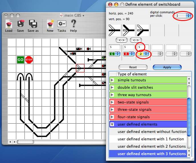
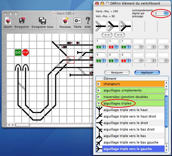
If the turnout is already defined inside the ECoS/CS or compatible digital central unit, then you must use a different definition when using the "direct" syntax (see page 21): in this case the threeway-turnout must be defined inside the switchboard as an element with only 1 digital command per click. You can select the graphic out of the list of the predefined "three way turnout"-elements as well, but you must redefine the number of digital commands per click to 1 (popupmenu in the upper right corner of the definition window)! The title of the switchboard-element will change into "user defined element with 3 functions".
The state "right" must be assigned to the lower accessory-decoder address (and the turnout itself must be connected this way). In the example below you will see the correct settings for a threeway-turnout assigned to the addresses "5" und "6" (please obey: the third state must be set to "6g", although the switching will go to "round"):

*
*
Threeway-Turnout defining when using an ECoS, CS or compatible device;
commanding via the regular syntax:
If there are turnouts already defined inside the ECoS/CS, then the "regular" syntax should be used to command accessories. The digital central unit is knowing what kind of accessory it is switching, and SDL will receive correct events relating to the states of the accessories. If you are using an accessory-address-translation table you can still use the already known accessories' real addresses. In case of the threeway-turnout the switchboard-element must be defined with only 1 digital command per click definiert werden. The third state must be defined as "2". The same has to be defined if you are using the device's database-IDs (>= 20000). The example below shows the correct settings for a threeway-turnout assigned to the addresses "5" und "6" when using a translation table (please obey: only addresse "5" has to be commanded):
|
|
|
|
|
|
the authors

http://www.oocities.org/fischer_familie/

|
|
|
|
|
Hinweis zu Links:
Mit dem Urteil vom 12. Mai 1998 hat das Landgericht Hamburg entschieden, dass man durch die Ausbringung eines Links die Inhalte der gelinkten Seite ggf. mit zu verantworten hat. Dies kann, so das LG, nur dadurch verhindert werden, dass man sich ausdrücklich von diesen Inhalten distanziert. Mafi verweist auf seinen Seiten mit Links zu anderen Seiten im Internet. Für alle diese Links gilt: Mafi erklärt ausdrücklich, dass ich keinerlei Einfluss auf die Gestaltung und die Inhalte der gelinkten Seiten habe. Bei Linksetzung wurden die Inhalte nach bestem Wissen geprüft, da aber eine spätere Veränderung der gelinkten Seiten nicht verhindert werden kann, distanziere ich mich hiermit ausdrücklich von allen Inhalten aller gelinkten Seiten auf allen meinen Homepages und mache mir diese Inhalte nicht zu Eigen. Diese Erklärung gilt für alle angezeigten Links und Banner und für alle Inhalte der Seiten und Banner, zu denen Links führen und zu deren nachgeschalteten Seiten.
Ferner gilt: bei direkten oder indirekten Verweisen auf fremde Internetseiten, die außerhalb des Verantwortungsbereiches des Autors liegen, würde eine Haftungsverpflichtung ausschließlich in dem Fall in Kraft treten, in dem der Autor von den Inhalten Kenntnis hat und es ihm technisch möglich und zumutbar wäre, die Nutzung im Falle rechtswidriger Inhalte zu verhindern.
Der Autor erklärt daher ausdrücklich, dass die gelinkten Seiten zum Zeitpunkt der Linksetzung nach bestem Wissen auf rechtswidrige Inhalte geprüft wurden. Der Autor hatte und hat zu keinem Zeitpunkt Einfluss auf den Inhalt der gelinkten Seiten.
Aus diesem Grund distanziert sich der Autor hiermit ausdrücklich von allen Inhalten aller verknüpften Seiten, die nach der Linksetzung verändert wurden. Für illegale, fehlerhafte oder unvollständige Inhalte und insbesondere für Schäden, die aus der Nutzung oder Nichtnutzung solcherart dargebotener Informationen entstehen, haftet allein der Anbieter der Seite, auf welche verwiesen wurde, nicht derjenige, der über Links auf die jeweilige Veröffentlichung lediglich verweist.
|
|
|
|
|
|
|
|
|
|