
12) 16-inch Gun Technical Data
Updated: November 28, 2004
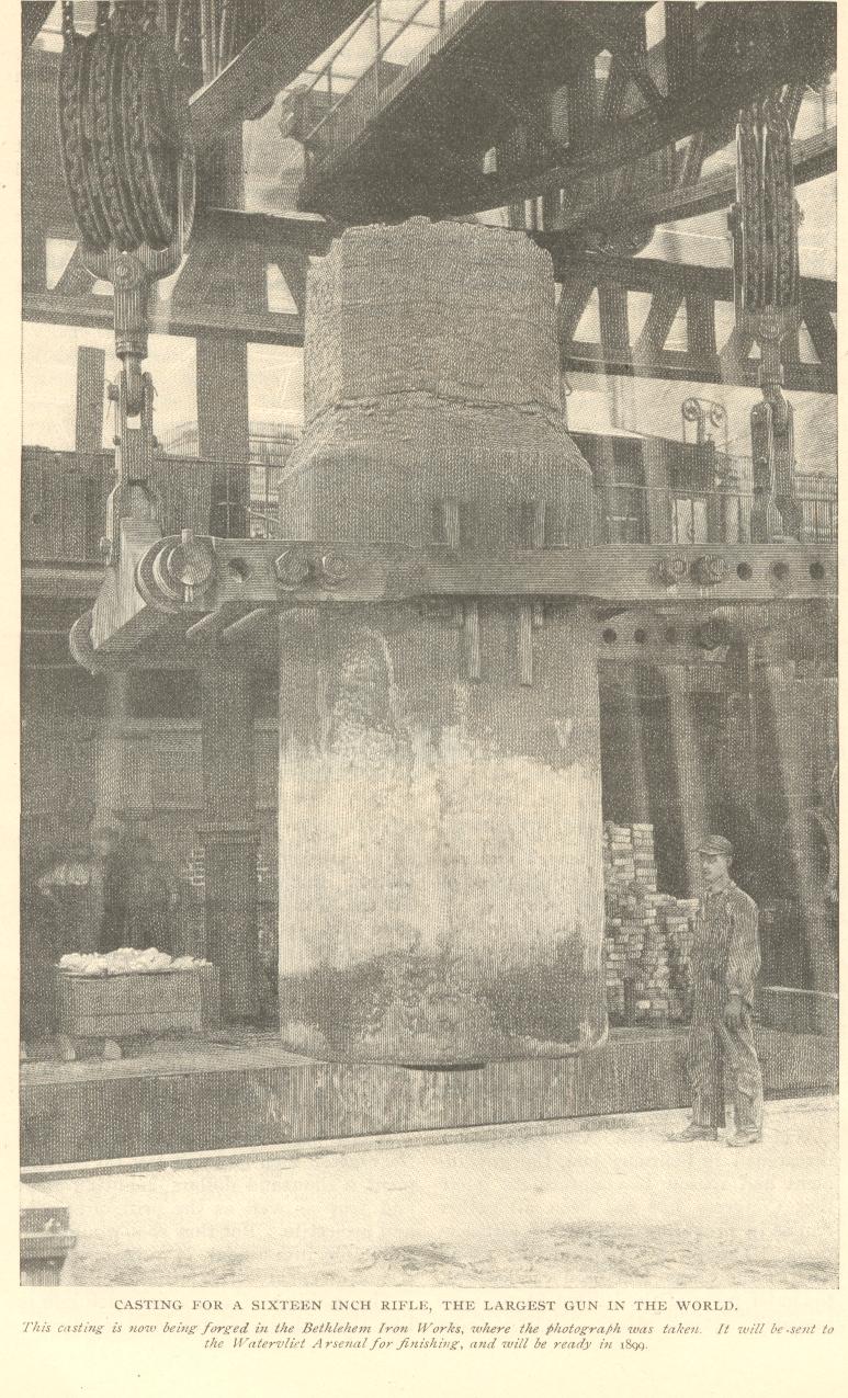 Photo: The Prototype 16-inch Gun at Sandy Hook Proving Grounds, NJ
History:
The original plans to build the first American 16-inch gun were approved in 1895, and the first 16-inch gun was built by the Watervliet Arsenal, NY, in 1902. It was 39 feet long (35 caliber), 5 feet in diameter at the breech, had 1-50 to 1-25 gain twist rifling (explained below), and weighed 284,000 pounds. It was tested at the Sandy Hook Proving Ground, Fort Hancock, NJ,
and returned to Watervliet in 1917 for refurbishing.
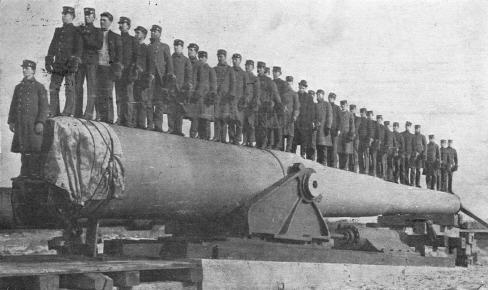
 Photos: The Prototype 16-inch Gun at Sandy Hook Proving Grounds, NJ
Special thanks to Jeff Arban for these postcards!
It was later sent to Battery Newton, in Fort Grant, at the Panama Canal Zone and mounted in a disappearing carriage until it was scrapped in 1943.
The second gun Model 1919, was a 50 caliber (66.6 feet long) gun with 1-32 rifling, which weighed 340,000 Lbs. This gun was mounted at Battery JMK Davis, Fort Michie, Great Gull Island, NY, until it was scrapped in 1943.
In 1917, Congress approve three sites to receive M1919 guns, Battery Williston at Fort Weaver in Oahu, Hawaii, Battery Harris at Fort Tilden in Rockaway, NY, and Battery Long at Fort Duvall near Boston, MA.
In 1922, twenty M1919 Mk II Navy guns were transferred to the Army, six of these were installed between Fort Kobbe, Panama, and Oahu, Hawaii. In 1938 six, 2 gun batteries were approved for the continental United States. Twenty Batteries were in service at the end of WW2, and eighteen more were incomplete or cancelled.
Different 16-inch Guns:
- 16" gun 35 caliber, gain twist rifling (only one manufactured),Watervliet (installed at Battery Newton, Perico Island, Panama).
- M1919 50 caliber, 1-32 rifling (only one manufactured), Watervliet (installed Battery Davis, Ft. Michee, on a M1917 disappearing carriage).
- M1919 M-II and M-III, 50 caliber (Army), Watervliet (used on barbette mounts - six rifles appear to have been manufactured).
- M1919 Mk I Navy, 45 caliber(Colorado Class Battleships).
- Mk II Navy (Army modified), two separate members, Watervliet.
- Mk II M1 Navy, different propelling charge, WNY.
- Mk III Navy (Army modified), minor differences with Mk II barrel hoops and rings.
- Mk IV.
- Mk V Navy.
- Mk VI Navy, 45 caliber for North Carolina (and South Dakota) Class battleships.
- Mk VII Navy, 50 caliber for Iowa Class battleships, Watervliet, Bethlehem, and Midvale.
- M1920 16-inch Howitzer (see photo below)
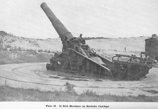
Photo: M1920 16-inch Howitzer on M1920 Carriage
Carriages:
M1 no shield, 65 degree elevation, mechanical rammer
M2 2 inch shield, 47 degree elevation
M3 2 inch shield, new type elevation buffers, heavy floor beams
M4
M5
M1920 carriage for M1920 16-inch Howitzer
Surviving 16-inch guns:
Mk II Navy Model (gun tube only) - Washington Navy Yard (WNY),
Washington, DC
Mk II Navy Model (gun tube only) - Dahlgren Naval Surface Weapons
Center, VA
Mk II Navy Model (gun tube only) - Dahlgren Naval Surface Weapons
Center, VA
Mk III M1 Navy #138, on Barbette Proof Carriage S/N 1 Aberdeen Proving Ground, MD

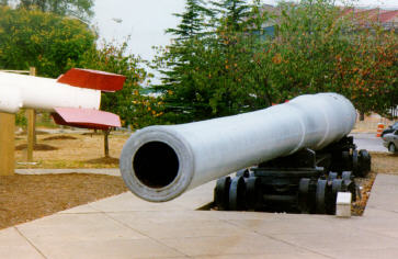

Photo: Mk II Navy Model at the Washington Navy Yard, Washington, D.C.
(Private Collection 1999)
Technical Information:
The following technical information will address key features of both the M1919 and M1920 16-inch guns from the breech to the muzzle.

Firing Lock:
The Mark I firing lock was used for the combination Percussion-Electric Primer Mk XV MI, that was used to initiate firing. The mechanism has a hammer to strike the primer mechanically, and an electrical terminal connected to the
insulated firing pin that provided the current path for electrical firing.

Photo: Firing Lock MkI for 16-inch Gun.
Combination Percussion-Electric Primer Mk XV MI:
This primer was inserted into the obturator spindle at the rear of the breechblock and retained by the firing lock. The black powder charge in this primer was either electrically or mechanically initiated by the small primer cap located within the primer.
Photo: Combination Percussion-Electric Primer Mk XV MI
Breechblock:
The breechblock of these guns was the step-thread type, or "Welin" type, mounted on a hinge located below the breech. Compressed air was used to close the breech.

Photo: Step-Thread Breechblock.
Debange Obturator:
These guns were equipped with the "DeBange
Obturator" as part of the breech. This device was used to seal the breech to prevent the damaging escape of hot propellant gases during firing. These guns used a powder charge contained in cloth bags instead of a one-piece brass cartridge. When a gun with a brass cartridge is fired, the obturation is performed by the case expanding and preventing any gas from escaping through the breech. Such guns do not require any obturator mechanism.
The DeBange system used a central, steel mushroom shaped head (item 14) which was mounted in front of a gasket system (items 9, 10, 11, 12, 15). When the gun was fired, the pressure of the the gases pushed the mushroom head against the gasket causing it to expand and seal the breech (item 1) and the barrel (item 2). The spindle of the head (item 7) was drilled to allow the flame from the primer (at 5) to ignite the powder charge (at 13).
The spindle was mounted with a ball bearing (item 3) to allow rotation of the breech without the drag of the obturator adding additional effort. One man should be able to turn the obturator with effort.

Photo: DeBange Obturator
Powder Charge:
The nitrocellulose powder charges were contained in cloth bags that were made from a special raw silk known as "cartridge cloth". This cloth burns without leaving any smouldering residue in the barrel which would present a safety hazard when loading the subsequent round.
The number of powder charges loaded, along with the elevation of the barrel, would determine the range of the gun. Depending on the specific type of gun and the projectile used the powder charge would vary, but for maximum range the charge would be six bags of powder (648 or 672 pounds) for the Navy MkII M1 gun, to four or eight bags of powder (total charge of 832 pounds) for
the Army MkII and MkIII guns.
Photo: Powder Charge
Projectiles:
A variety of types and different weight projectiles have been
manufactured over the years for these guns. Armor Piercing (AP) shells weighing either 2,100, 2,240, and 2,340 pounds were typically used by the coastal
guns.
Photo: Armor Piercing Shell for the 16-inch Gun
Photo: Test Damage to Armor of Japanese Ship from 16-inch Gun
(Private collection 1999, Washington Navy Yard)
Here is a message from Shawn Welch concerning this photo: This is a really interesting story related to me by FCCM (sw)
Stephen Skelley (Navy's Master Gunner for 16-inch). The plate in your photo is a face plate from a Yamato Class battleship turret (yard item) and is 26 inches thick. The plate was pierced
by a 2,700 lbs projectile simulating an impact at about 30,000 yards of range. The test proved clearly that in a fight with an IOWA, the Yamato's immunity zone was much smaller than originally thought, and would have been at a disadvantage.
The neat part about the test is there is another plate at the Navy yard that is connected to this test. That plate is the roof of Turret 1 from the USS South Dakota. During the Battle of Santa Cruz in 1942, a Japanese dive bomber scored a direct hit on the roof of turret #1. The crew of the turret did not know what happened (and continued normal duties). The center gun of Turret #2 was right over the detonation point and the rifling was badly scared. When the gun was removed during the repairs required for battle damage sustained by USS South Dakota after the night action of November 1942 (where the battleship USS Washington sunk the Japanese Battleship Karishima), the gun was returned to the factory and relined. It subsequently was sent to Dahlgren to be used as a test weapon, and fired the
rounds that tested the Japanese Armor plates.
Thanks for the info Shawn!
Barrel:
The barrel of this gun was made by wrapping steel wire around an inner tube. This wire-wound construction utilized square cross section wire, about 0.1 inch per side, wound at constant tension. Additional layers of wire were wrapped at the breech end so the barrel could withstand the maximum pressure developed in this area. The outer hoops and tubes are then installed by
shrink fitting them over the wire windings. This process made it possible for this large gun to be manufactured without having to cold-work the gun from a massive single forging.
The caliber of these guns were usually 45 or 50. The term
"caliber" refers to the ratio of the length of the barrel to the diameter of the bore. A 50 caliber gun with a 16 inch bore will have a barrel length of 800 inches or 66.6 feet. (16" x 50cal = 800 inches/12 inches per ft = 66.6')
The rifling of this gun was right-handed, which means that the projectile will rotate clockwise when viewed from the rear. Early 16-inch guns had "gain twist rifling" that had an initial twist of 1 turn in 50 caliber that increased to 1 turn in 25 caliber at a point 2 calibers (32 inches) down the barrel. The rifling remained at 1 turn in 25 caliber twist throughout the remainder of the barrel. This special type of rifling acted to reduce the strain on the soft copper rotating band of the projectile during the maximum acceleration near the breech, but was found to be impractical due to manufacturing difficulties and the fact that this actually increased the drag on the projectile in the barrel. Later guns were produced with rifling of uniform twist.
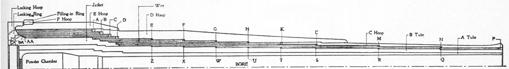
Photo: 16-Inch Gun Barrel Cross-Section.
The Gun Carriage:
Since the total weight of the 16-inch gun and carriage was over 660,000 pounds, rotation of the gun for aiming was an obvious problem. This was solved by using 44 conical roller bearings arranged in a circle and mounted under the carriage to allow the entire assembly to be rotated easily by one man using a crank handle. Later carriages used an electric motor and a Waterbury gear box that allowed the gun to be traversed quickly and then
slowly to allow precise azimuth setting. The traverse of the gun is unlimited unless the gun is casemated. The traverse of a casemated 16-inch gun is physically limited to 145 degrees by the concrete casemate walls.
Elevation of the gun is made easier by virtue of the gun being
muzzle-heavy when it is unloaded. This allows an operator to spin the elevation hand wheel to drop the gun into the loading position (elevation of about 4 degrees, depending on the specific model). Once the gun is loaded with the projectile and powder bags, it is now breech-heavy, thus allowing the operator to again spin the elevation hand wheel in the opposite direction
to now lift the gun into the firing position. Anti-friction bearings on the trunnions, combined with this well-designed balance of the gun allow the gun crew to easily elevate the gun using the manual hand wheel, or the electric elevation motor system. Maximum elevation is 65 degrees, but if the gun is casemated the elevation is limited to 47 degrees. Two semi-circular racks on each side of the gun and a pinion gear are the elevation mechanism.
The power rammer used to load the gun is part of the carriage allowing the gun to be loaded while remaining pointed at the target azimuth. Circular railroad tracks surround the gun to bring the powder and projectiles directly to the gun breech area. When the gun is casemated, a overhear trolley system is used to bring both powder bags and the projectiles to the gun from the internal magazine areas of the casemate. In this case the gun was traversed to it's central postion to allow the ammunition to be lowered into the power rammer from the trolley hoist riding on the fixed overhead rail system.
Recoil Mechanism:
The recoil mechanism utilized two long, and two short cylinders as well as two oleo-pneumatic recuperators to return the gun to battery. The air side of the recuperator was charged to 1,700 psi with air and the oil side was filled with a 60% glycerine and 40% water mixture to prevent freezing. As the gun recoiled the air pressure increased to approximately to double the 1,700 psi precharge.
Subcaliber Gun:
A 75mm gun was mounted above the main gun tube for training purposes to allow gun crews to practice firing drills without using expensive ammunition. The 75 mm M1916 gun or the 75mm M4 gun was used for this purpose.
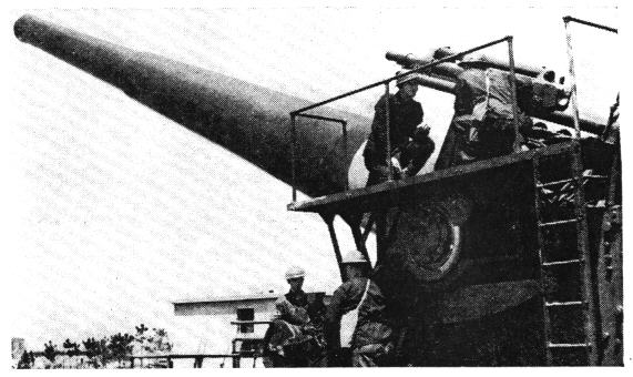
Photo: Subcaliber Gun on top of 16-inch Gun at Fort Tilden.
Firing the gun:
The firing of this gun was similar to the detonation of any large quantity of explosives. A "firing train" of successively larger charges was used to insure the proper ignition and complete combustion of all of the main charge. When the firing lock hammer was tripped by a lanyard or by the application of an
electric current, the small primer cap within the primer ignited the black powder in the primer, which fired a jet of flame through the vent in the obturator spindle, which in turn ignited the igniter charge of black powder located on the back of the rearmost powder bag.
This ignited the main charge contained in the powder bags, which would continue to burn while the projectile was forced out of the barrel. The soft copper rotating band on the projectile engaged the lands of the rifling in the barrel and forced the projectile to rotate. This rotation stabilized the projectile in flight and provided for accuracy. Once the projectile cleared the muzzle, any unburned powder would continue to burn, but would not increase the velocity of the projectile, since the expanding gases in the barrel could no longer exert any force on the rear of the projectile.
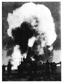
Photo: Firing the 16-inch Gun at Fort Tilden (circa early 1941).
Cleaning the Gun:
Just like any other gun, the M1919 required cleaning after firing to prevent the barrel from corrosion. Long rammers with burlap tips were dipped in a solution of soap and water to clean the barrel. All parts were cleaned and oiled to prevent the salt air from corroding the steel parts.
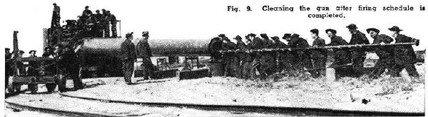
Photo: Cleaning the 16-inch Gun at Fort Tilden (circa early 1941).
Casemated 16-inch Gun Batteries:
In 1940, just prior to America's entry in World War 2, many new 16-inch coast artillery gun batteries were installed around American harbors. Massive concrete casemates were constructed for these twin gun batteries. These batteries were designated as "100 Series" batteries and were named after they were completed. These concrete casemates protected the guns from naval bombardment and air attack. Contrary to popular myth, the casemates were not constructed to prevent the guns from being "turned around to shell the city".

Photo: Casemated 16-inch Gun Battery at Camp Hero, Montauk, NY
The End of an Era:
At the end of WW2, the massive 16-inch guns and carriages of Fort Tilden were cut into pieces with torches and sold as scrap metal. The concrete casemates remain today as the only remnant of this "Golden Age" of Coast Artillery. A 16-inch gun on a barbette proof carriage is on display at the Ordnance Museum at the Aberdeen Proving Ground, in Maryland.
Sources of Data:
ROTC Manual, Coast Artillery, Basic, 10th Edition, 1938
US Army TM 9-2300, pages 142 thru 145
Watervliet Arsenal Museum
Science and Mechanics Magazine, Oct-Nov 1941 issue
TM 4-210, Coast Artillery Weapons and Material (1940)
TM 9-471, 16-inch Seacoast Gun Material, Gun, Mk-II M1 (3 Nov 1942)
SO30-BA-HBK-010/BB61 CL, Battleship 16"/50 Caliber Gunnery
Handbook (15 May 1988)
E-mail from Shawn Welch dated 9/4/2000