TrikiBoard 2
Before reading this page, I hope you have already read the Triki Board Overview.
Block Diagram of TrikiBoard-2
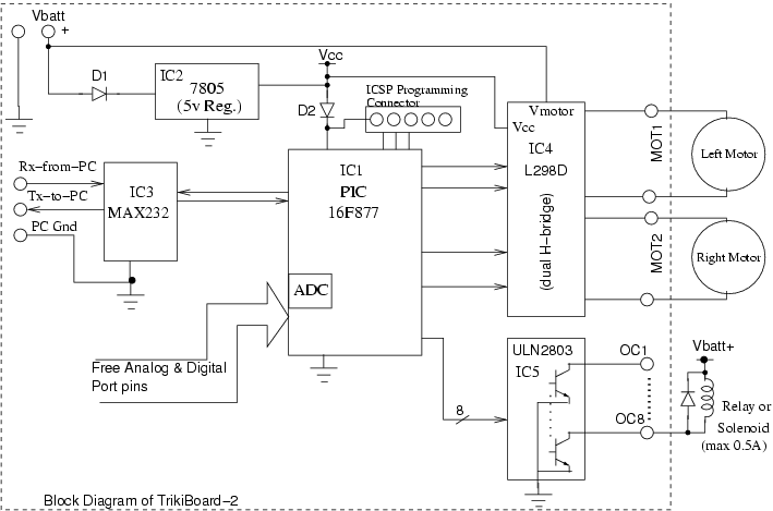
In the block diagram of TrikiBoard-2 above:
-
All connections to/from the Board are shown by small circles.
-
IC3, MAX232, is used to connect to the PC by serial port. This connection is useful for debugging and controlling the robot by issuing the command through the keyboard of the PC. Though in real autonomous run of the robot, this connection would be taken off.
-
IC4, L298D, is a dual H-Bridge DC motor driver.
-
IC5, ULN2803, is a Darlington Transistor Array (with 8 transistors), for Open Collector (OC) outputs.
-
Diode D1 is for Reverse Battery Protection. (a common thing when you fumble in hurry to connect the battery of your robot at the time of the contest) :)
-
Diode D2 stops the Supply of the ICSP programmer from going into the rest of the circuit, except to the Microcontroller (MCU).
Download
-
The Schematic as an Image or pdf.
-
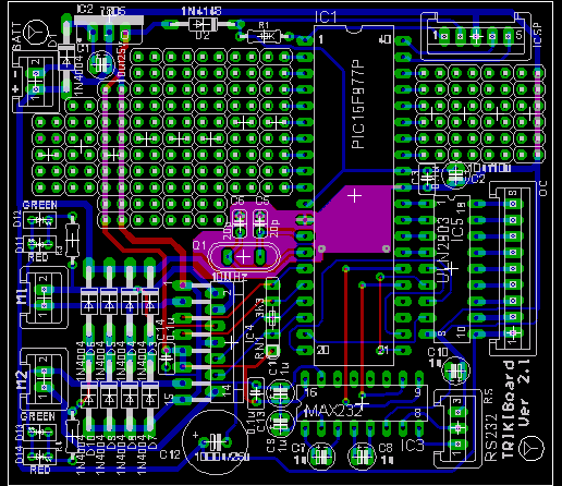
This is how the PCB layout looks
-
The complete Schematic and Board files for Eagle. (Eagle PCB Layout software can be downloaded from www.cadsoft.de)
-
You can directly print Bottom Layer and Top Layer of the Board by these pdf files.
-
You should print this Component Layout pdf file to begin soldering the board
-
This is the Parts List. Read below to see if you need to buy some chips or not.
How to Make it
To get the PCB made:
The process to get the PCB made has 2 steps:
-
Make the film from the BRD files or Gerber files
-
Make the PCB from the film
Step 1: Getting the Film Made:
-
Either use the Board file (.brd) for Eagle, and generate the Gerber Files by the procedure mentioned here, and give all these files to your PCB maker. (In Mumbai, you can email the Eagle .brd file directly to Image & co., and call them on 28347898. They will make the "films or photoplots" of your pcb, which you'll give to any PCB maker.) Get the Silkscreen Film (for printing of labels) also done if you can spend a little more. (Approx cost of all photoplots with legends Rs. 400-450 at Image - from gerber file).
-
Or print the Top and Bottom layer PDF files on a 1200 dpi laser printer, and give the printout to your PCB Film maker or PCB maker directly. I do not recommend this method as the print quality may not be good, and tracks may get shorted. But this is the last resort usually of the Non-Metro residents.
-
Getting the Film made from a printout (the second method above) is usually less expensive but the quality may not be proper. Your Film-maker will tell you if he can make it from the printout you'll give to him after looking at it. (approx cost is 25paise/cmsq).
-
Getting the Film made from the Gerber File is more expensive, but the quality is best. It would be better if many friends share the cost of a common film. (In IIT, one of the Yantriki coordinators may get many PCBs made in bunch after finding out the demand, as was done a few years ago).
-
IITan's can also try getting their complete PCB done in the PCB facility of EE dept for free. But that pcb would not have component names printed on it & no green paint. Moreover the dept. facility may not allow too many PCBs of the same type because the tool there is much much more expensive in its running cost.
Step 2: Getting the PCB Made:
-
Just give the Film to PCB maker. (Some vendors in Bombay are listed on the Vendors page here.)
-
IMPORTANT: Tell the PCB maker to drill, 0.8mm holes for the L298 & 7805 chip. If the holes are not big for these 2 chips, the chip wont go in the PCB and whole PCB would be useless.
Soldering:
-
Refer to the Component Layout PDF file and Parts List while soldering.
-
Follow the usual soldering procedure: Solder IC Sockets first, and the components with lowest height first. Thus capacitors, connectors and 7805 go to board last.
-
RN1 is a Single-in-Line Resistor pack (called SIP resistor in market). Use 3.3K sips, with 4+1 pins. The common pin, denoted by a dot, goes to Vcc (+5v) track.
How to Use TrikiBoard
As mentioned earlier, TrikiBoard Version 2 is very simple board just to give a head-start to Yantriki Level 3 participants who need a Microcontroller Board to control their robots, and it forms a base for EDL Beginners if all they need is a Serial Link to PC or Memory interface to mcu to check their initial project designs.
Power Supply: Apply 8 to 12 volts through the connecter labeled 'Vbatt'. This Battery voltage shall be used to drive the motors by the board. The 7805 chip on-board shall produce 5 volts for the microcontroller. If the 7805 or L298D gets heated too much on your board, add a Heatsink to these chips. Commonly available 7805 would require a heatsink.
Program the microcontroller with simple test programs first like blinking an LED first. Then write bigger code.
Provisions on TrikiBoard ver. 2.1
Dual H-Bridge for DC Motors
The board can drive 2 DC Motors (which maybe wheel-drive motors). The chip L298D is Dual H-Bridge chip. The motor directions are controlled by the 4 port pins as follows
| RC0 | RC1 | Motor 1 (MOT1) |
| 0 | 0 | Off |
| 0 | 1 | Forward |
| 1 | 0 | Reverse |
| 1 | 1 | Off |
| RC2 | RC3 | Motor 2 (MOT2) |
| 0 | 0 | Off |
| 0 | 1 | Forward |
| 1 | 0 | Reverse |
| 1 | 1 | Off |
Speeds of the Motors can be controlled by generating a PWM on these Port pins by the PWM generators built in the PIC.
| PWM Pin | Direction Pin | Motor |
| CCP2 (pin 16) | RC0 | Motor1 |
| CCP1 (Pin 17) | RC3 | Motor2 |
| Whenever PWM and Direction pin will output the same Logic Level, the Motor would be OFF. | ||
See a quick explanation of how PWM is used to control the speed .
In other mechatronic applications, a Bi-polar stepper motor (usually 4-wire type) can also be controlled if its 2 windings are connected to MOT1 & MOT2 connectors instead of 2 dc-motors. (see below).
The 2 on-board LEDs associated with each Motor can be used for debugging. Red LED would signify one motor direction and Green the opposite. The L298 can drive practically 12V, 1A consuming motors by each driver.
NOTE: The actual Voltage supplied
to the DC motor would be = Vbatt - Vdrop_in_L298D_IC
The usual drop on the transistors
inside the L298D is 1.5 to 2.5 Volts. Hence if your battery Voltage is 12V,
assume that the motors would practically run at about 10V.
Though the TrikBoard is protected against reverse battery connection, the L298D IC gets the Vbatt supply directly, and hence, is not protected by diode D1. (so that there is no loss in Motor Voltage due to Vdrop_D1). Hence don't take things for granted while connecting the battery.
Running 2 Stepper Motors
Click here to see how different kinds of Stepper Motors can be connected to TrikiBoard-2.
RS232 Port
A serial link can be established between a PC and TrikiBoard by EDL junta if needed, and Yantriki users for debugging (Note: in actual Yantriki Contest (maze-solving) no off-board link/processing is allowed).
If needed, connector named 'RS' has to be connected to the the 9-pin Serial connector of the PC as follows.
| RS Port Pin on TrikiBoard-2 | PC 9-Pin D-type connector |
| RS-3 (Gnd) | 5 (Gnd) |
| RS-2 (Tx) | 2 (Rx) |
| RS-1 (Rx) | 3 (Tx) |
Hyperterminal in windows can be used to check the serial link. Use a simple serial test program to just send a character on the serial port, and see it on the Hyperterminal screen after setting the proper baud rate etc (the same which you set in the code of the MCU).
15 Digital IO Lines and 8 Analog lines and prototyping Area
The 15 digital lines are available on pin headers JP1 & JP4. Out of these, 8 can be used as ADC input lines of the MCU, when enabled by software. The general purpose PCB area can be used to add simple sensor amplifier circuits etc.
NOTE the Vcc and GND tracks
running on the 2 columns of the holes on this general purpose area.
The power supplies for the extra
circuits/sensors can be taken from these tracks.
Programming
To write and simulate programs you can download PIC cross assembler tools from Microchip. There are plenty of other VERY useful software and APPLICATION NOTES on the Microchip site.
The "Hex files" generated after compiling the code, are to be burned in the
microcontroller using a programmer.
Either you can make this programmer yourself as shown in the
JDM PIC Programmer for On-Board Programming of the PIC MCU.
OR you can use the device-programmer of your
college. (For IITians in the EE Dept. WEL Lab). The
code can be written in C or ASM (free cross compiler for ASM only). use google.
Sample & Test Code
--
Sorry I haven't yet got time to make the Sample and
Test Code for this. But goggle would lead
you to tons of Sample PIC code, which you can adapt for the PIN assignment of
this board.
Sensor Links (Yantriki Level 3 specific)
Sensors associated circuits are deliberately not provided with TrikiBoard, because there can be too many sensing styles, strategies, and circuits, there is lot of scope of innovation here.
The reason TrikiBoard was designed, is that many needed a microcontroller board to run their algorithms on, and were trying to find ways to mount the the usual 8051 Kit on the robot.
Here are some links which could be useful, but I guess you can do a better google search and spend more time searching circuits (or making your own).
-
http://www.electronic-circuits-diagrams.com/alarmsimages/alarmsckt19.shtml The circuit given on this site will have to be modified so instead of the relay you get the signal +5 to 0 level. The Sharp Module is not sold as sharp module in Indian Market, but just say "TV ka IR remote detector, 3 pin wala" in market. Its tuned frequency might be a little different but within +/-3 KHz usually.
-
http://www.gorobotics.net/IRPD2.shtml. Again the detector used is the "TV wala".
Vivek Vaid
vivekvaid<|a-t|>iitb_ac_in
(for email address: replace <|a-t|> by @ above and _ by . )