| S-video To Composite Video |
This simple adapter can be used to convert Y/C video (S-video) to a composite
video. This adapter is useful in cases where your video output device has only
S-video output but your signal source accepts only composite video input. This
circuit works with both PAL and NTSC video standards.
Y-ground------------------+
                          +---------- RCA/composite ground
C-ground------------------+

Y-------------------------+
                          +--------- RCA/composite video
C------------||-----------+
            470pF
This circuit can be quite easily build inside a the S-video connector
case if a physically small size 470 pF (ceramic) capacitor is used. Larger
capacitor values will also work, but cause picture to become "softer". The
voltage rating of capacitor can be 10V or more.
This circuit works in practice quite well even though the circuit operation
is not ideal. This means that impedances and signal levels not matched exactly
right, but near enough to work accetably. The picture quality you get from this
circuit is is good, but not as good as with best possible composite video output
circuitry.
Here is the pinout of the S-video connector shown from the end with the
FEMALE PINS (picture is a view on the equipment back/front panel):
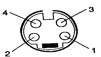
1   Y ground
2   C ground
3   Y (luminance+sync)
4   C (crominance)
What if my PC graphics card has a 7-pin S-video connector instead of 4-pin
?
The four pin S-video connector as shown above is the standard connector for
carrying S-video. Those seven pin connectors seen on some PC graphics cards are
non-standard connectors for carrying S-video. The use of the pins on those seven
pin connectors is not standardized and can vary from manufacturer to
manufacturer. (For some strange reasons some manufacturers in PC industry just
keep constanly breaking the industry standars and create lots of confuzion to
users when doing so).
Generally the four pins on those 7-pin connectors on the same places as the
standard four pin S-video connector have practcly always the same fuctionality
as those pins in S-video connector. The other three pins can have then some
extra signals which are not part of S-video (usually some pins of those carry
composite video and some control signals, but the use of those three extra pins
vary quite much). So if you encounter 7 pin connector for S-video, then forget
the three center pins... just use the four on the standard positions. The
circuit shoudl work with those connectors as well.
Can the circuit used in other way ?
If you try to connect the circuit in opposite way so that you have a
composite video signal which yoiu want to feed to S-video input then you might
wonder would this circuit work also in that way. The answer is that the circuit
sort of work also in this way. If you connect a comoisute video source to a
S-video input of your TV using this circuit, you will get a full color picture
on your TV screen. The downside of this is that the picture quality will be
worse than if you were using the real composite vidoe input of your TV. The
reason for this is that after the circuit the color information is still in the
brighness signal, you you see some interference on the screen caused by color
subcarrier which gets to the screen. This all means that you can use this
circuit as last change in situations where you don't have a composite video
input. The picture quality is degraded, but propably still usable for some not
so demanding applications. A real well working solution would be much more
complicated than this circuit.
|