Eric's R/C BOAT RACING
Click Here for: NitroTouring.com
| WHAT'S NEW | GALLERY | PROJECTS | SETUP | BOAT PLANS | LINKS |
|
Eric's R/C BOAT RACING Click Here for: NitroTouring.com
|
|
THUNDERCAT Fast Electric Racing Catamaran
Catamaran Hull taking care of business in the "rough". For a 18.5" hull those waves are HUGE. Intro: The newest hull to emerge from the my boat dock is a Jay Turner designed catamaran. Jay's XL-CAT is a light weight hull that boils the water with a modified motor on 6-cells. The first phase is the build phase. I purchased the plans from RCBM rcstore.com , I bought these plans over (2) years ago. I remember spending countless hours on the phone with the sales representative because the original shipment was sent to the wrong address -twice. I must of called everyone that worked there, even the managers where aware of my MIA boat plans. Two years latter, all the suffering has been worth it. The boat is built following the plans, but the building materials and building style are all mine. The original boat (the one that was used for the on the pond testing) Only had ply in the transom. This new boat that you see in the photos is much stronger than the previous design, and better profiled. I'm sure the finished hull will weigh in about an ounce heavier than the previous model, but the finish and strength will be better than the original. Sponson Construction:
Note: The original boat plans call for construction grade foam sponsons covered with airplane heat shrink wrap. I recently adquired the hardware to cut foam, but I'm still working on a jig that will allow me to make consistent cuts with foam. Nothing is lighter than air, but incase of an accident ply covered foam sponsons are very tough and usually let you finish the race. No comment on the hollow 4 chamber Eric "air" sponson. Don't get me wrong my design is stiff and very light, but it will suffer major damage if someone mistakes my boat for a turn buoy. It could turn into a titanic... Tunnel/ Main Hull Construction:
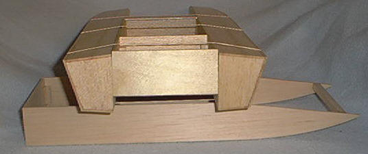
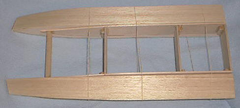
The main hull is built up from 1/8 h_balsa sides with 1/8 h_balsa bulk-heads. The transon is laminated with 1/16 ply on the outside and 1/32 in the inside for strength. The front of the tub is further reinforced with (3) 3/8X3/8 balsa sticks. Note: Skeleton view shows only one piece. The top and bottom of the tub are sheeted with 1/32 ply. There will be a 1/16 ply doubler installed underneath the engine mount when it's placed in the tub. You have to build the hull light but there must be a stiff connection between the motor mount and the transom.
Build tip: I found it to be easier to install all the hardware on the tub before attaching it to the sponsons. This way you can work with the boat without having to worry about dinging up the sponsons as you handle the hull with the dremel and the drill in hand. You could go both ways but if you do assemble the hull before the hardware you should go ahead and seal, prime and finish the outside of the boat. This will add needed strength to the soft outer 3/32 balsa sheets. Assembly of the hull:
The tub sides and the sponson sides are then sanded w/ 200 grit sandpaper. You can use thick CA or 5 minute epoxy to join both parts together. It is important to assemble the three parts on a smooth flat surface. You need to maintain a 3/4 " tunnel depth between the bottom of the tub ans the bottom edge of the sponsons. I happened to have some square 3/4 tall aluminum tube. I placed a couple of the pieces under the flat portion of the tunnel. I then pressed the sponsons to the center hull making sure everything was at 90 deg angle. After you are sure everything lines up perfect, separate the sponsons and glue into place. If using epoxy you can run a bead of CA along the outside seam of the tub/sponson to keep everything aligned as the epoxy sets. In the photos I use rubber bands to keep the hull together for presentation purposes only. When you actually do it the 10 finger technique should be adequate. Hardware installation: Hardware installation is fairly straight forward. I choose to put the rudder on the right side of the boat. The enclosed radio box offers plenty of space for separate receiver packs if you need to use one and full size servos. Note the mount for the water pickup tube on the left sponson. The hole above the strut bracket is for the aluminum water cooling tube that goes across the radio box. Never allow any water-to-tube couplings inside of the radio box. One faulty connection and you will submerge your electronics...
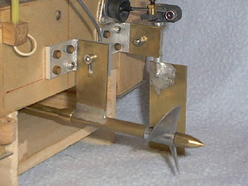
The hardware is mostly hand built from K&B brass sheet and tubing. This photo shows a 3/16 strut but the 05 powered version should use the 1/8 stub shaft for the smaller props. Remember the finished boat RTR is 32 Oz. very light, so you will need a fast revving motor w/ a small prop. With good batteries and a water cooled motor you should be able to prop up to a 35mm size prop.
The strut and rudder brackets are made with 3/32 aluminum angle cut about 5/8" long. They are strong and light. Remeber there should be near zero flex in the drive-line and hardware. If the prop or the rudder happen to hit something other than water, the single 3mm cap head screw will let the hardware kick back to "save" the transom from being ripped of the boat. You also have to keep in mind not to over tighten this screw. The brackets are secured to the transom w/ 4-40 cap head screws. Drill the holes 2-steps smaller than the screw diameter. Use a stainless steel 4-40 screw to form the threads into the wood. After you make the threads, back out the screw apply a drop of thin CA and re-thread the screw. The resulting threads will be strong and very tight. If you feel that they are too tight you can run a 4-40 tap partially into the screw hole to help you start the screw.
Here is the original boat with the 1/8 stub shaft propeller shaft and the light weight aluminum blade rudder assembly. That's me adjusting the strut height. notice the water cooling system. Water is picked off the rear of the sponson ride pad and channeled to the motor brush coolers. The water then exits through an aluminum tube glued into the right sponson (not shown). Hull Setup: Radio Gear: Since the radio box is so spacious you can ran just about any size servos and receiver that you want. For directional control I choose a Traxxas standard servo, a little slow but more than enough torque to steer this small light hull. I chose a Futaba Radio/Receiver combo to keep everything in check. Hardware: The Flex cable is .098 with a 1/8 stub shaft soldered in place. The strut uses lead-Teflon bushings with a 1/8 drive dog. The motor mount is from Warehouse Hobbies (The Enforcer People). The rudder and strut are home made from brass and soft solder. Motor: I happened to have a Kyosho 14 Turn Double 05 motor. They have a machine wound armature w/ a large diameter commutator. This coupled with fat 4X4mm brushes means good power and low wear. Powering the motor is a sport 6-cell 1500 Sanyo saddle pack. Speed Control: I recently got a digital FMA-Direct Hi-Frequency speed control. It is their sport model good for motors down to 12 turns @ 75 amps. Not to sure about the amp draw numbers. They seem quite inflated to me, still the speed control is only warm after a 3 minute run. Props: With no water cooling, I liked the performance of the Octura X431 direct drive with the 14T motor. With water cooling and better batteries I think X432 or X435 should be other alternatives. With a 19T Single armature (Chameleon) running in a water cooled Trinity Paradox can the motor pulled an Octura Y535 with out a lot of problems.
On the water testing will be available in part 2 of the ThunderCAT Article series. Available soon...
|

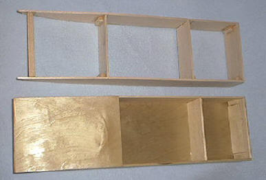
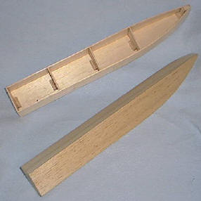 Here
we can see the hollow sponson construction. The wood is sealed both on the inside
as well as the outside with spray polyurethane. The side of the sponson, the one that attaches to the
boat is 1/8 hard balsa. The top, bottom and sides are 3/32 hard balsa. The
bulk-head reinforcements are 1/8 h_balsa. 1 inch 3/8 X3/8 balsa sticks are used
for strength and to help keep the structure warp free as the sponson is being
built.
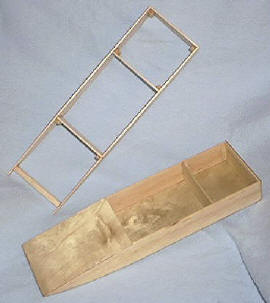
Here
we can see the hollow sponson construction. The wood is sealed both on the inside
as well as the outside with spray polyurethane. The side of the sponson, the one that attaches to the
boat is 1/8 hard balsa. The top, bottom and sides are 3/32 hard balsa. The
bulk-head reinforcements are 1/8 h_balsa. 1 inch 3/8 X3/8 balsa sticks are used
for strength and to help keep the structure warp free as the sponson is being
built.