![]()
![]()
Ic(H)? Is it dumb and simple or powerful and complex? Introduction.
Ic(H) does not work or behaves strange or hangs up. What is wrong?
The measurement of Ic(H) dependence is one of the most advanced algorithms in GoldExI featuring:
measurement
of Ic for IVC with hysteresis
The
current which passes through the sample should be denoted as sweep1.
Measure IVC. Make selection as shown above and zoom. Repeat zooming if necessary until you get the following picture:
To
compensate zero-shifts of voltages, use AutoZero. If AutoZero works
correctly you should see zero average voltage of the noisy trace, as
in the above figure.
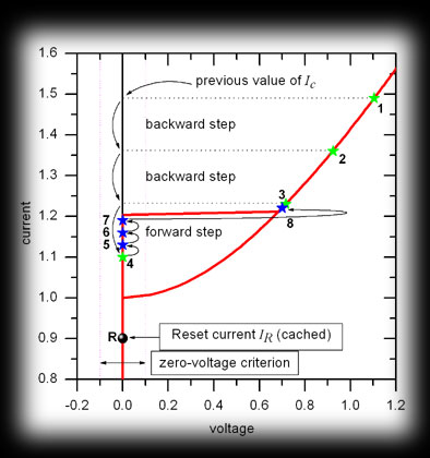
Let us present a sample IVC (see picture below) and outline the algorithm used by GoldExI to measure Ic(H).
Remember that a distinction between zero voltage state (V=0) and resistive state (V>0) is given by criterion, i.e., in description below, when we compare V with zero, we actually compare V with criterion Vcr. If V<Vcr, we assume that V=0, if V>Vcr, we assume V>0.
If you have checked "use |V| instead of V" in Ic(H) options, the V in the above conditions becomes |V|.
The procedure is the following:
GoldExI sets the bias current equal to the value of Ic found for the previous value of field, or, in the case of the very first point, just the value which was set by the user in the Measurements|Ic(H) window.
[Going down]: The voltage V across the sample is measured. If V=0, this means that the bias point is on the Meissner branch, and we go to the next step of the algorithm. If V>0, the bias point is on the resistive branch. GoldExI performs the reset (roughly speaking by setting bias current I=IR, see the above figure), and then biases the junction to the point 2, i.e. applies the bias current that is somewhat lower than in point 1. Then GoldExI repeats the current step from the very beginning.
Thus, for our example above, it goes to the bias point 2, V>0, resets, goes to bias point 3, V>0, resets, goes to the bias point 4. At the bias point 4 V=0, so we go to the next step.
The distance (in current) between bias points 1 and 2 or between 2 and 3, is called "Backward step" and can be set in Ic(H) Options window.
[Going Up]: Now as we are in the Meissner state, i.e. at I<Ic, we increase the current by a tiny amount and check the voltage. If V=0, we repeat this step, until V becomes >0.
Thus, for our example above, GoldExI goes to the bias point 5, V=0, goes to the bias point 6, V=0, goes to the bias point 7, V=0, goes to the bias point 8. At the bias point 8 V>0, i.e. we actually found Ic, and we go to the next step.
The above mentioned tiny steps are called "forward steps" and can be set in Ic(H) Options window.
[Maximizing Ic]: Sometimes it happens that critical current is not stable or multi-valued, i.e. Ic which was found on the previous step corresponds just to the accidental switching of the sample. In this case it is usually interesting to find really the maximum critical current. For this, GoldExI makes several efforts to reset and then to set the current which is one "forward step" higher than before. If it is successful (V=0), then it tries to go up further until the sample switches to the resistive state. Then GoldExI again resets, and makes another effort to maximize Ic.
The "number of efforts" corresponds to the number of resets+1 done during the above maximization procedure and can be set in Ic(H) Options window. The "Number of efforts"=1 means that maximization will not be performed.
[Resetting to get Ic]: Up to now we know how much current we had to pass (to set) to be just below Ic. So, as we are now in resistive state, we perform another reset, and set the current to that sub-Ic value. Then we measure this current and add the data point to the Ic(H) dependence.
The value of magnetic field (sweep2 current) is changed and we repeat the whole algorithm from the very beginning.
First, let us show some sample picture (below) where 2 IVCs for the previous and the current values of magnetic field are plotted.
To perform a reset:
In the beginning, regardless of the current bias point, GoldExI sets the current to the cached value of reset current IR. If there is no cached value (as in the very beginning), the current bias point is used. For our example above, the cached value of IR corresponds to the bias point 1 in which the previous IVC had V=0 (black point), but current IVC, may have V>0.
If V>0, then we try to decrease the current by some amount which is called "step while searching V=0" ("SWS V=0" for short), and check the voltage again, i.e. we repeat this step until we get V=0.
Thus, for our example above, GoldExI goes to bias point 2, V>0, goes to bias point 3, V>0, goes to bias point 4. At bias point 4, V=0, so we go to the next step.
The above mentioned "step while searching V=0" can be set in Ic(H) Options window.
Since V=0, the reset is complete and we can save the current value of current as IR for the future use.
Note, that the above algorithm can only decrease the value of IR , i.e. during measurement IR moves more and more down to lower currents and can even end up on the negative part of the IVC. This may result in poor performance since GoldExI should go too far to reset the system. In addition, when one "uses |V| instead of V" (see Ic(H) options), if IR jumps to the branch V<0, this will result in termination of the algorithm as zero-voltage state can not be found in spite of the maximum negative current was applied.
To cope with the above issues, GoldExI has a mechanism which allow IR to increase, if possible, with time. This mechanism is very simple. Instead of trying cached value of IR as first candidate for reset bias point, GoldExI tries somewhat higher value, see bias point 1a in the above figure. This value of bias differs from IR by an amount which is called "Reset stabilization step" (or RSS for short).
The value of RSS can be set in Ic(H) Options window.
When RSS>0 the above example will work as follows. GoldExI goes to the bias point 1a, V>0, goes to the bias point 2a, V>0, ..., goes to the bias point 5a, V=0. Reset is complete, the new value of IR is cached, see the figure.
If you have IVC with a series resistance as shown in the figure below, GoldExI can compensate for this resistance and you still can measure Ic(H). To turn this mode on do the following:
Measure IVC at H=0 and (in addition to the noise and zero shift) determine the series resistance. You may want to use cursors (Ctrl+R) for this.
Go to Ic(H) Options window and check "Compensate for series Resistance", and input the value of resistance in the corresponding field.
During the measurement GoldExI uses leaned criterion as shown in the following picture.

"Reset H to init. value during reset". This allows to keep H=H_init (H_init is the value set before you have clicked "Do It" button) during each reset procedure. Pitfall: If reset is reached for H_init, it does not garatees that the sustem will be in the reset state when GoldExI sets actual value of H! Use with care.
"Reset bias before measuring Ic". When GoldExI finds the maximum value of sweep1 which can be set so that the volatge across the sample is still zero, the magnitude of the current actually flowing should be measured. The simplest approach is to set sweep1 current back the the pre-critical value and measure it. The problem is that when GoldExI has found Ic, the sample is in resistive state, so, in the case of hysteretic IVC, setting the current back to pre-critical value will not bring the system to precritical zero-voltage state. Present option "Reset bias before measuring Ic", allow to reset sweep1 first, and then go to precritical value. This may be very useful if you work with non-ideal current source (or high resistance sample), so that the current which is actially flowing depends on the voltage across the sample. Pitfall: The fact that reset is performed, does not guarantie that after sweep1 is set to pre-critical value the voltage will be non-zero. Due to fluctuations, the bias point may jump to resistive branch. GoldExI does not check this at the moment. This check may be implemented in the future, if user's feedback will indicate nessecity.
"AutoZero sweep1 currents for each H". Sometimes (e.g. when one works with SQUID amplifier) zero of the measurement setup shifts as a function of sweep2 (e.g. magnetic field). In this case, GoldExI can call AutoZero for each value of sweep2. This slows the measuremts, of course.
"Delay after each reset". Measuring small samples or applying high current through them, may result in heating effects when the bias point jumps to the resistive branch. Therefore, next immediate measurement of Ic may give wrong Ic value (decreased due to heating). Usually resulting Ic(H) curve will look erratically. To circumvent this problem, the "Delay after each reset" was introduced. According to Ic(H) algorithm, after the bias poit jumps to the resistive branch, the reset follows. Then you can set "Delay after each reset" to wait few ms (or sec?), to let your sample cool down.
GoldExI starts measuring and them stops showing an error message. Read the message, it should say you the reason.
Ic(H) is very slow. Try to tune parameters as described in "Tuning Ic(H) performance".
Ic(H) hands just after you have pushed "Do It" button. Probably your initial bias point is not well selected and performance options are poorly tuned, so that it takes ages for GoldExI to find Ic and IR for the first time.
When sweep IVC using oscilloscope, I see that IVC is unstable (jumps). For such IVC the measurement of Ic(H) is very slow. This is normal.
If your wish to see in which phase of Ic(H) GoldExI spends most of the time or hangs, use mark "Show Ic(X) progress messages" in Ic(H) options window. During Ic(H) measurement you will see what GoldExI is doing step by step as explained in "Searching Ic" and "Resetting". Remember that this may substantially slowdown the measurement.
First of all try to understand where GoldExI spends majority of time. As a rule, the time killers are:
improperly
chosen value of zero-voltage criterion
First of all criterion should be chosen as small as possible but larger than the noise amplitude.
Small "Forward step" results in higher accuracy of Ic, but proportionally slower. The recommended1 value is 1 bit for 12-bit DAC cards, and 8 bit for 16-bit DAC cards.
The value of "backward step" should be a bit larger than the value of "forward step" since, in general, backward step is more expensive in terms of time. While forward step sets sweep1 current, waits, and reads the voltage, the backward step in addition makes reset i.e. performs at least one additional "set current, wait, get voltage" sequence. The recommended1 value is 2..3 times larger than the one of "forward step".
"Number of efforts">1 may noticeably slow down measurements when IVC is unstable, but otherwise decreases performance just by few percents.
"Reset searching step" (also called "step while searching V=0") should be large enough to pass the whole IVC in few seconds, but small enough not to pass zero-voltage region (reset region). Recommended1 value is 128 for 16-bit cards, and 8 for 12-bit cards.
"Reset stabilization step" can be chosen approximately equal to the above "Reset searching step".
"Maximum DAC step" (see Options | Delays) is a way to protect the sample from sudden jumps of bias current. Instead of jumping directly from I1 to I2, GoldExI sets the current several times smoothly changing the set value from I1 to I2. If "Maximum DAC step" is too small, such sequence like "try I, V>0, reset, try lower I" may result in hundreds or thousands of "set current" commands. On the other hand setting large value increases the probability that your sample will be shocked by a bias current. The recommended1 value depends on the sensitivity of your sample. I use 256 for 16-bit cards, and 8 for 12-bit cards.
(1) The above recommended values are given for the case of no averaging and short delays<10ms.
I hope that statistics is self explanatory :-). If not, write to me and ask your question.
See also: .
![]()
[Review]
[Download]
[Gallery]
[Links]
[F.A.Q.]
[HerStory]
[Bugs]
[Suggestions]
[Author]
[EMDAQ.DLL] [Home]
[forum]