source
The unified modeling language user guide
by- Grady
Booch
James Rumbaugh
Ivar Jacobson
MODEL
A model is a simplification
of reality. We build model so that we can better understand the
system we are developing and it often expose opportunity
for simplification and reuse. Model help us to communicate the
desired structure and behavior of the system. Model give us a template that guide us in
constructing a system.
UML
The 'UML' is a modeling language. A modeling language is a language whose vocabulary and rule focus on the
conceptual and physical representation of a system. It helps in communicating
the conceptual model of a program to others.
Second , it is difficult to understand the class hierarchy by staring
at the code. UML helps in such case.
Third , if the developer who cut the code never wrote down
the model that are in his or her mind, that information is lost forever
or at best , only partially retractable from the implementation once that
developer moved on .
UML address the third issue also. Each symbol in the UML notation is a
well defined semantic . In this manner one developer can write to another
developer or even another tool
can interpret the model unambiguously.
UML address the documentation of a system's architecture and all
of its detail. The UML also provides a language for expressing requirements
and tests. UML provides a language for modeling the activities of project
planning and release management.
Building blocks of UML
the things ,relations and diagrams are the three
building block of the UML.
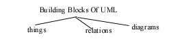
Things are the abstraction that are first class citizen
in a model ; relationship ties these things together ; diagram
group
interesting collection of things.
The things (building block
-one)
the things are basically of four types
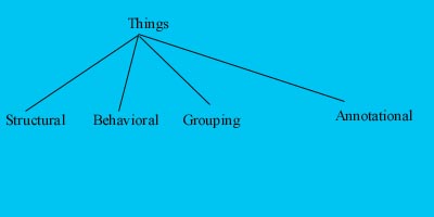
1. Structural things
:--
are the nouns of the UML model , representing
elements that are either conceptual
or physical
There are 7 kinds of structural
things.
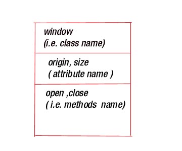
1) Class :- is a description
of a set of objects that share the attributes
and semantics. A class implements
one or more interfaces .
Graphically class is denoted as a rectangle in
following manner .
2) Interface :- An interface
is a collection of operation that specify a service of a class or component.
It defines a set of operation specifications ( that is , there
signature ) [ thus the externally visible
behavior of that element] but never
a set of operation implementation.
Graphically it is denoted by a circle ; together with its name.
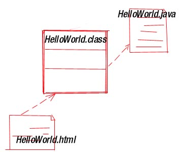
3) Collaboration :- defines
an interaction and is a society of roles and other elements that work together
to provide some co-operative behavior that's bigger than
the sum of all the elements .
Graphically - ellipse with dashed lines usually including
only its name.
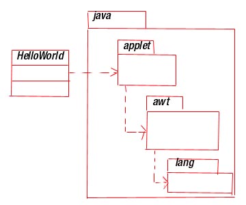
[ an example
import java.awt.Graphics;
class HelloWord extend java.applet.applet{
public void paint (Graphics g)
{
g.drawString("HelloWord",10,10);
}
}
[ modeling after coding is called
reverse engineering ]
Here import java,awt.Graphics directly available
to the code that follows
( java.awt prefix specifies the Java
package in which the class Graphics lives )
The second line of code class HelloWord
extend java.applet.applet introduces
a new class named applet which lives in the package
java.applet ]
Here HelloWord collaborates directly
with only two classes namely Applet and Graphics .
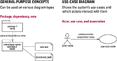
4) Use case :- is a description
of set of sequence of actions that a system performs that yield an
observable result of value to a particular actor .
Graphically an ellipse with solid lines , usually including only its name.
Use case describes what a system does but does not specify how it does all.
An actor represents a coherent set of roles that
user of use cases
play when interacting with these use
case, communicate with one another , each one
possibly sending and receiving messages.
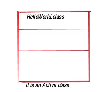
5)Active class :- is just
like a class except its objects represents
elements whose behavior is concurrent with
other elements.
Graphically:- similar to the class but with heavy line.
(An active class is an class-
whose objects own one or more
processes or threads and therefore can
initiate control activity )
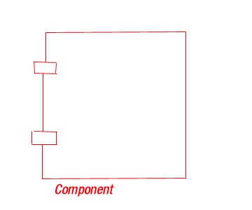
6) Component:- is a physical
and replaceable part of a system that conforms to and provides the
realization of a set of interfaces.
A component typically represents the physical packaging of otherwise logical elements , such as classes ,
interfaces , and collaborations.
Graphically :- a component is rendered as a rectangle with tubes usually including only its name .
It is usually have higher level of abstraction than classes.
PHYSICAL VIEW OF APPLET :-
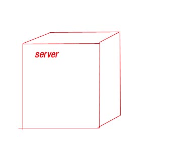
7) NODE :- is a physical
element that exist at runtime and represents a computational resources , generally having
at least some memory and often , processing
capabilities set of components may reside
on node or migrate from node to node
Graphically :- a node is rendered as a cube , usually including name.
2) Behavioral Things :-
are dynamic parts of UML models. These are the
verbs of a model , representing behavior over time and
space
There are two primary kinds of behavioral things
:-
1) Interaction :- is a
behavior that comprise a set of message exchanged
among a set of objects within a particular context to accomplish a specific purpose.
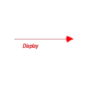
Graphically a message is rendered as a directed line , almost
always including the name of its operation.
2) State machine :- is
a behavior that specifies the sequence
of states an object or an interaction goes through during its lifetime in response to events
together with its response to those events.
A state machine involves a number of other elements ,
including states , transition ( the flow from state
to state ), events (things that trigger
a transition and activity ( the response to a transition)
Graphically , a state is rendered as a rounded
rectangle usually including its name and its sub states.

3) Grouping Things :-
are the organizational parts of UML model . These are
the boxes into which a model can be decomposed.
A package is a general purpose mechanism for organizing elements into groups structural things behavioral
things and even other grouping things
may be placed in a package.
Graphically a package is renders as a tabbed folder usually including only its name and sometimes its contents
.
4 Annotational things :- are
the explanatory parts of UML models . These are the comments you may apply to describe
, illuminate and remark about any element
in a model .
Graphically a note is rendered as a rectangle with
Dog-eared corner ; together with a textual or graphical
comment.
BUILDING BLOCK-2
There are four kinds of relation
ships in the UML.
1) Dependency :- is a
semantic relationship between two things in which a
change to one thing ( the independent things)
Graphically it is shown by dashed possibly directed toward,
independent thing.
2) Generalization :- is
specialization generalization relationship in which
objects of the specialized elements ( the child ) are substitutable for
objects of the generalization element( the parent) ( Here the child has all the structure
and behavior of a parent and may has some addition
properties )
Graphically a generalization on relationship is rendered as a solid line with a hollow arrowhead pointing to the parent.

3) Realization :- is
a semantic relationship between classifiers , wherein
one classifier specifies guarantees to carryout . Realization relationship
is somewhat a cross between dependency and
generalization and its notation is a combination of the notation for
dependency and generalization .
Graphically a realization is rendered as a dashed line with a large open arrowhead pointing to the classifier that
specifies the contact.
exp.- In Java program . by using
a keyword interface , you can fully abstract
a class interface from its implementation . Interface are syntactically similar to classes, but they lack instance
variable ( i.e. there instance can't be created ) and their methods are declared .without any body(i.e. they are abstract
method - they always overridden access
interface name {
return type ( int/ void ...)
method name
( parameter list );
}
The interface gets realized only
when it is implemented
by some class . A class
may implement a number of interfaces and an interface
can be implemented
by a number of classes .
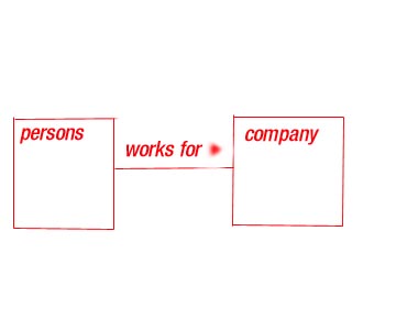
4)Association :- An association
is a structural relationship that specifies
that object of one thing are connected to object of another . Given an association connection two classes ., you can navigate
from an object of one class to an object
of another class and vice versa.
Graphically an association is rendered as a solid line connecting the same or different classes . Use association
when you want to show structural relationship
.
Beyond this basic form ,there are
four adornments that apply
to association .
NAME - To avoid ambiguity
, you use the name to describe the nature
of relationship.
You can give a direction to the name by providing
a direction triangle that points the
direction you intend to read the name.
ROLE:-When a class participates
in association it has a specific role that
it plays in that relation ; a role is just the face the class at the near end of the association presents to the
class at the other end of association.
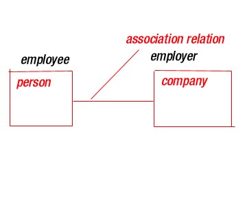
MULTIPLICITY :- An association
represents structural relationship
When you state ( number like shown in figure )
multiplicity at one end of the association , you are specifying
that for each object of that class at
the opposite end , there must be that many objects at the near end.
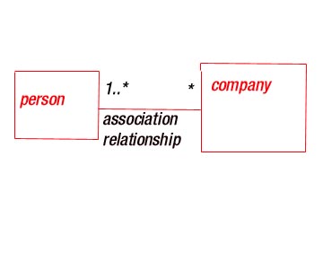
Here for each company their must be one or more
person.
other multiplicity notation
0....1 zero or one
(1) exactly one
0....* zero or many
0..1,3..4,6..* ant # other than 2 & 5
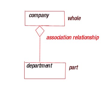
AGGREGATION :- When one
class represents a larger things ( the whole
) which consists of smaller things ( the parts ) .This kind of relationship
is called aggregation is really just
a special kind of association and is specified by
adorning a plain association with an
open diamond at the whole end , as shown in figure
.

BUILDING BLOCKS -3
DIAGRAM
1) class diagram :- shown
a set of classes , interface and
collaboration and their relationship .
2) object diagram :- shows
a set of object and their relationship
3) use case diagram :-
a set of use cases and actors.
Interaction diagram :- shows an interaction , consisting of a set of objects & their relationship , including the
message that may be dispatched among
them.
4) A sequence diagram :-
is an interaction diagram that
emphasizes time-ordering
5) Collaboration diagram :-
is an interaction diagram that emphasizes
the structural organization of the objects that send and receive message.
6) A state chart diagram :-
shows a state machine , consisting of states,
transition events and activities .
7) Activity diagram :-
is an special kind of a state chart diagram
that shows the flow from activity to activity within system.
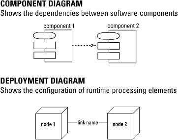
8) Component diagram :-
shows the organization and dependencies
among a set of components.
9) Deployment diagram
:- shows the configuration of run-time processing
nodes and the components that live on them .
(click here )
for more information on object oriented analysis and design
( click here
) to download business process modeling
with UML


