| Since the TS series of pedals is covered in depth by R.G. Keen's The Technology of the Tube Screamer article, it's only really necessary to cover what changes were made to the original design. | ||
| The Changes | ||
| Changes were made in only a couple of areas. With the 'Boost' Control,
the pedal can be set up such that it has minimal distortion for light playing
with the drive control and the Boost can be used to set up a much more
aggressive, overdriven tone. It also provides true bypassing. By changing
just two capacitor values the low-frequency response is improved significantly.
I'll separte the changes as much as possible to help illustrated what change affects what characteristic. Most of which could be applied to any TS series pedal to help 'customize' it to the players individual wants or needs. |
||
|
|
||
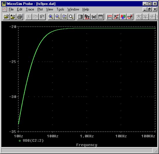
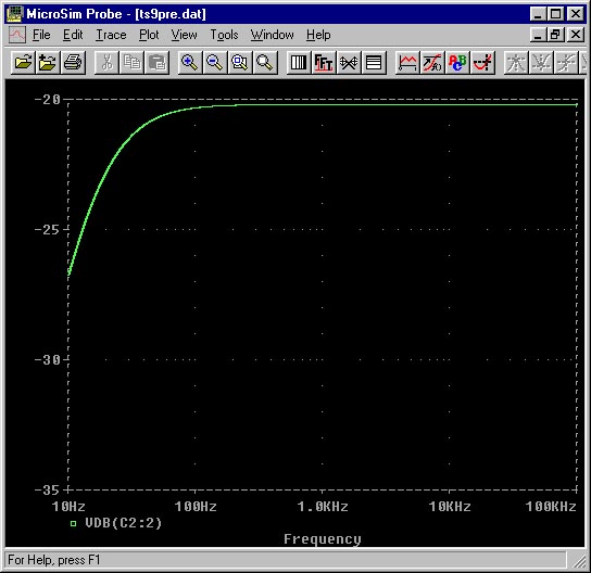
 The
0.02uF capacitor on the input of the Buffer transistor causes some of the
Low-Frequency Rolloff typical in the TS-9. In order to increase the 'Bottom
End' , this capacitor can be increased. The first plot below shows the
frequency response of the stock TS-9 circuit. If this capacitor is changed
to a 0.1uF the low frequency response is increased. The trick is to not
allow too much low of the low frequencies into the frontend of the clipper
circuit to cause the pedal to start sounding mushy. The clipper section
has it's own low-frequency rolloff components but before anything can be
increased at that stage, it has to be allowed to get there to begin with.
If you look closely at the simulation plots of the clipper section you
can see the break point where the filtering of the clipper stage takes
over from the filtering of the front end. The
0.02uF capacitor on the input of the Buffer transistor causes some of the
Low-Frequency Rolloff typical in the TS-9. In order to increase the 'Bottom
End' , this capacitor can be increased. The first plot below shows the
frequency response of the stock TS-9 circuit. If this capacitor is changed
to a 0.1uF the low frequency response is increased. The trick is to not
allow too much low of the low frequencies into the frontend of the clipper
circuit to cause the pedal to start sounding mushy. The clipper section
has it's own low-frequency rolloff components but before anything can be
increased at that stage, it has to be allowed to get there to begin with.
If you look closely at the simulation plots of the clipper section you
can see the break point where the filtering of the clipper stage takes
over from the filtering of the front end.
|
||
|
|
||
 The
clipper adds some of it's own low-frequency rolloff in the the combination
of the 4.7k and .047uF capacitor. By increasing the capacitor the low frequency
response can be increased. To achieve the ability to adjust the drive down
to a minimum amount of clipping, the 51k was reduced to a 22k. The combined
resistance of the 22k and the Drive control determine how much gain the
stage has before the diodes breakover. The 22k allows the drive to be adjusted
such than the diodes will only break over on signals 100mv(peak) or greater
at 1KHz. With the addition of a Boost control in series with the Drive
control, it's not necessary to have full range adjustability in the Drive
control. The value of the drive control was therefore reduced to 250k.
The values of filter resistor, filter capacitor, and series Drive resistor
all interact in determining the overall frequency response and gain. The
clipper adds some of it's own low-frequency rolloff in the the combination
of the 4.7k and .047uF capacitor. By increasing the capacitor the low frequency
response can be increased. To achieve the ability to adjust the drive down
to a minimum amount of clipping, the 51k was reduced to a 22k. The combined
resistance of the 22k and the Drive control determine how much gain the
stage has before the diodes breakover. The 22k allows the drive to be adjusted
such than the diodes will only break over on signals 100mv(peak) or greater
at 1KHz. With the addition of a Boost control in series with the Drive
control, it's not necessary to have full range adjustability in the Drive
control. The value of the drive control was therefore reduced to 250k.
The values of filter resistor, filter capacitor, and series Drive resistor
all interact in determining the overall frequency response and gain.
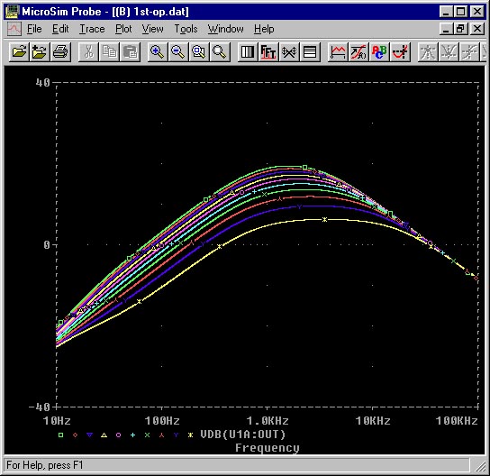
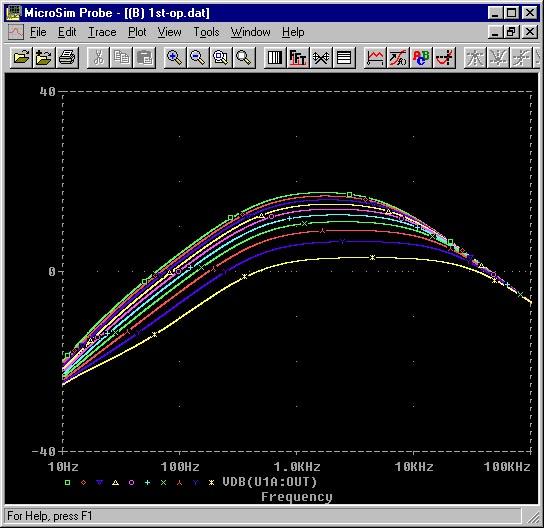
The two plots below are of the clipper section. The plot on the left
is for the stock TS-9 circuit. The plot on the right is with the 4.7k changed
to a 3.3k and the .047uF changed to a .1uF. The combination of the two
strikes a compromise between increased low-frequency response and gain-reduction.
|
||
|
|
||
 The
tone control was left intact as it exists in the TS-9. The response of
the stage is determined primarily by the 0.22uF/220 ohm series combination
connected to the wiper of the control. When the control is set to the center
position it has a flat frequency response. The high-frequency rolloff is
determined solely by the 1K and 0.22uF to ground on the input to the control.
Depending on which side of center the control is turned, it provides either
high-frequency boost or cut. The first plot below shows the tone control
stage by itself. The second plot shows the response when the 1K/.22uF network
is included. The
tone control was left intact as it exists in the TS-9. The response of
the stage is determined primarily by the 0.22uF/220 ohm series combination
connected to the wiper of the control. When the control is set to the center
position it has a flat frequency response. The high-frequency rolloff is
determined solely by the 1K and 0.22uF to ground on the input to the control.
Depending on which side of center the control is turned, it provides either
high-frequency boost or cut. The first plot below shows the tone control
stage by itself. The second plot shows the response when the 1K/.22uF network
is included.
The third plot shows what happens to the frequency response when a 100 ohm resistor is added in series to the first .22uF capacitor (after the 1K). This results in leveling off the midrange bump somewhat and allows more variance with adjustment of the tone control. It gives it a somewhat more full sound and less harsh.  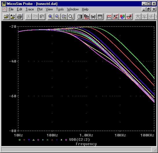 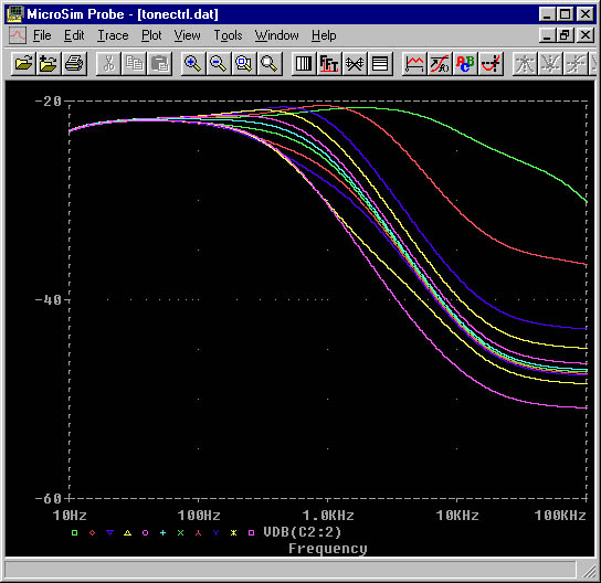 |
||
|
|
||
From a waveform point of view, it's possible to see what the different
drive level settings do to the level of clipping. These similations show
the unmodified TS-9 design first and the effect of the changes that were
outlined above. The plots were made using a 600Hz waveform because this
low enough were the differences can more readily be seen.
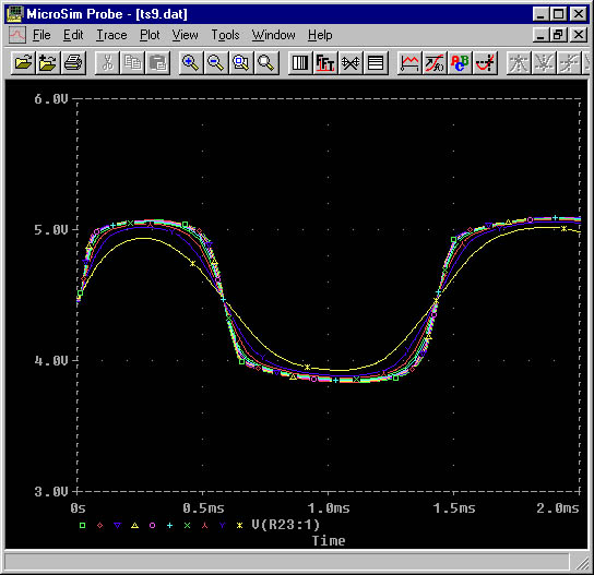 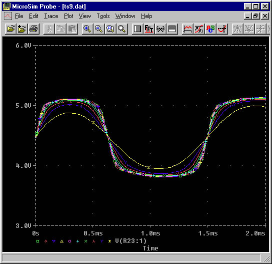 With the addition of the Boost control, the value of the drive control
can be reduced to give a more fine adjustment. With a 22K series resistor
replacing the 51K in the TS-9, the gain is even further reduced allowing
for a more 'clean' signal than the TS-9.
|
||
|
|
||
|
The Boost control allows an instantaneous increase in the amount of 'Drive' control. In addition, the 150pF capacitor provides some additonal high frequency rolloff removing some of the harshness resulting from the higher gain and imparting a slight tonal difference. 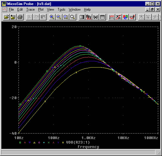 |