 Radio
Boy
Radio
Boy
Satellit 650 Adjustment/Routine
maintenance.
If you have just
bought a 650, and are not sure if all is OK with it, or if yours not behaving
like it should, here are some of the common problems, and the solutions.
Compiled by, in no particular order, Adriano Tencati, John Black, Thomas
Baier, (who took all the photos except where otherwise indicated, visit
his website here) &
myself.
The Satellit 600
is similar in most respects.
As usual, all adjustments
are made at your own risk, although the procedures described are fairly
simple.
Disassembly
of radio, removal of chassis:
1. Unplug the AC mains cord,
remove the battery compartment cover and the D cells. The AA cells can
remain in place.
2. Set the radio face
down onto its front handles.
3. Loosen the three cross-head
screws on the bottom of the set, lift the lower end of the rear panel and
remove it by moving it upwards.
4. Return the radio to
its normal upright position.
Checking alignment
of the Preselector:
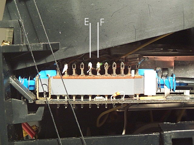
1. Short circuit contacts
"E" and "F" on FM selector with alligator clip (see pic below) after entering
each of the frequencies detailed below:
2. Select SW and enter
SW frequency 2050 kHz. LCD read-out should be: 19, (This applies to radios
with coverage to 30 MHz, for those with coverage to 26.1 MHz, and all Satellit
600's, which all have coverage only to 26.1MHz, the LCD read out should
be 20 instead of 19)
3. Enter SW frequency
23050 kHz. LCD read-out should be: "189", (This applies to radios
with coverage to 30 MHz, for those with coverage to 26.1 MHz, and all Satellit
600's, which all have coverage only to 26.1MHz, the LCD read out should
be 205 instead of 189)
4. Repeat same procedures
for LW and MW Band.
Below are the corresponding
frequencies and the LCD read-out for these bands:
LW: 160 kHz = 19
LW: 370 kHz = 199
MW: 560 kHz = 23
MW:1450 kHz = 212
5. If you preselector
is only slightly out, ie/ reads "20" instead of "19", I'd leave well alone.
it isn't possible to get it exactly right all across the bands anyway.
These check points are just 2 arbitrary points detailed in the service
manual. What is happening is that the software is dividing the preselector
tuning scale into 256 equal segments, and so a 1 in 256 error is of little
consequence. If you do want to correct it, you need to adjust 2 trimmer
pots, R827 & R829 on the variometer board. Circuit diagrams for the
600 are available at the Grundig
Satellit Warehouse, but if you don't know what you are doing, and can't
read circuit diagrams of such complexity, I'd recommend leaving well alone,
or getting a professional radio technician to do the adjustments. You could
make things worse.
6. When all done, don't
forget to remove alligator clip on FM selector contacts E and F.
Adjusting the
Variometer:
(Only necessary if auto preselector
does not match with max. signal strength in the above alignment checks).
If you don't want to adjust the trimmer pots as mentioned above, there
is another way, but it may improve one waveband (eg/ SW) at the expense
of the other 2 (LW and MW)
1. Enter a strong SW (or
LW or MW as desired) station, make sure auto preselector is on, and wait
until it has finished moving.
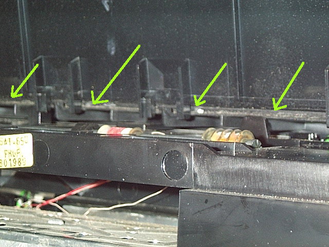
2. Move the Variometer
carriage carefully as follows:
a/ Push right toothed
rack down with "finger tip" and push the toothed rack a little bit
away from you. (see pic below)
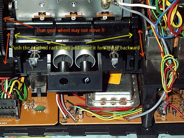
b/ Repeat procedure with
left toothed rack. Push it down carefully with a small screwdriver
Attention: Do not damage
toothed rack!
3. Enter frequency again,
and allow preselector to re-adjust. If it's now worse, repeat procedure
described under points a/ and b/ - but now move the toothed rack the other
way!
4. Check it by re-entering
frequency.
5. Repeat the procedure
until preselector matches 100 % with strongest signal!
Now you never have to
adjust the preselector in that part of the dial. you may wish to check
other parts of the SW band, and MW and LW, to confirm it's not been degraded
there.
Adjustment
of AM Signal Meter deflection:
1. Sit the opened radio in
normal position (Operating panel face towards you)
2. Locate the RF / IF
board (see pic below)
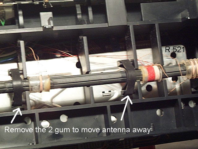
3. To ease access, you
may wish to remove the two rubbers (gum) from Ferrite antenna, to allow
antenna to be moved slightly out of the way. This isn't absolutely necessary,
however.
4. Enter the strongest
LW or MW or SW station you can get.
5. Adjust the Signal
Meter with a plastic screwdriver (NOT METAL!) by turning carefully the
resistor R513 left or right. (see Pic below)
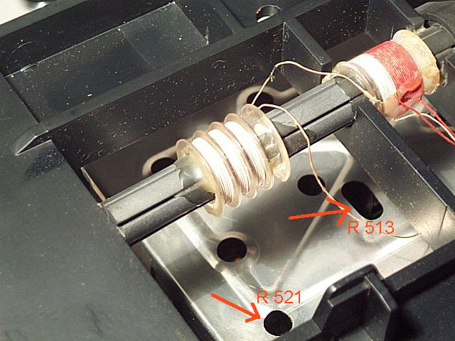
6. Readjust the Signal
Meter with a plastic screwdriver by turning carefully the resistor R 521.
(see pic above)
7. Check Signal Strength.
Enter an unused LW or MW or SW frequency.
Repeat procedure under
point 5 and 6. One pot controls the "full signal" deflection, the other
the "no signal" deflection, getting it right is a trial and error method,
but it will help if your meter never previously went beyond half deflection.
Note, this adjustment only affects the AM stages, FM is separately controlled,
and rarely needs adjusting.
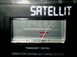
Note: A silent frequency
should bring the S-meter max to "1" A strong signal should bring S-meter
to "9", (see pic below)
Replacing bulbs:
1. With rear cover removed
as described above, and radio sitting upright, pull all the knobs off the
front, (volume/tone/bandwidth/SSB/AGC/clarify/pre-selector/tuning) and
then carefully slide the chassis back, out of the front panel. Be careful
while chassis is exposed, as wires are at risk, and circuit boards are
not fully supported.
2. The dial bulb is easily
accessed at the left hand side of the dial scale. the holder will pull
off carefully from the chassis. This bulb is 7V/80mA.
3. The tuning/battery
meter bulb is a push fit into the top of the meter, but first, you will
have to remove the meter from the chassis, by carefully pushing the locating
"tang" on the right hand side with a small screwdriver or similar tool.
Once the meter is freed on the right side, you should be able to coax it
out of it's space. This bulb is 7V/30mA.
4. The LCD is lit by
two 30mA bulbs as above, one on each side. The correct way to remove these
is to remove the LCD unit from the chassis, and there are 2 small holes
at the rear of the bulb holders to allow you to push the bulb out with
a straightened paper clip. (See below, photo by Adriano Tencati)
However, many people
will be nervous of disturbing the display, so here's another way to get
the bulbs out. Get a drinking straw that just fits reasonably tightly onto
the bulb (You will have the new spare one to try it on) and push it onto
the blown bulb, (see photo below). You can then pull the bulb out with
ease!

(Photo by me)
Two checks
worth carrying out, particularly on newly acquired 650's.
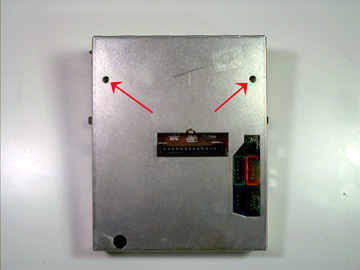
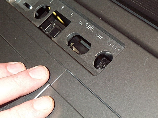
1/ Are any of the rotary
controls along the lower front "wobbly" (eg/ Volume/Bass/Treble)? If so,
don't worry, it almost certainly isn't because the control is worn out!
The actual control is bolted to the chassis, and if the nut, visible in
the photo above, has worked loose, the whole component will be loose. Simply
tighten with a spanner or pliers. These controls are usually rock solid
and smooth as silk.
2/ Try the headphone socket.
Does it work? If not, then try these other 2 tests. Set one of the timers,
and switch to auto. Does the radio come on when it has been programmed
to? No? Then turn it back on manually, select FM, tune to a strong station,
turn the speakers off, and turn the volume way up. Does the display keep
going off, or showing the "88888" error message? If so, don't worry, you
have a common, bad earth connection on the AF board. And it almost certainly
is because the connection, which goes across the ANL switch, has become
disconnected owing to the switch being used, and flexing the board. A quick
test with a resistance meter will confirm this, and simply touching the
2 terminals with a hot soldering iron will usually restore the link. It
is possible that the earth could fail elsewhere along the solder track,
but 99% of the time, it is here.
Two common
problems on this or any other second hand radio
I hardly need to tell you,
are corrosion in the battery compartment, for which you'll have to find
your own solution with a little ingenuity! The other problem I'm referring
to is a broken telescopic antenna. Now, while spare parts for this model
are almost certainly all gone now, thanks to the existence of the Satellit
800, and the fact that the designers were trying to copy the 650, they
have used the same antenna. Whether it is actually made by the same manufacturer,
or is actually a copy, I don't know, but I can't tell the difference if
it is. Fitting is simple! Remove the rear panel as described above. If
the old antenna is still in place, remove it by removing the 3/4 circle
circlip from the bottom of the stub, and pull the antenna right out. Remove
the circlip from the new antenna, push it into the antenna mount hole,
and refit the circlip. Job done! OK, I know what you're thinking! Where
do I get a new antenna? Simple. Contact Grundig
USA/Lextronix at the website, and ask for one. US$25 each at mid 2003,
might as well get 2 while you're there.
Reassembly
of chassis:
1. Carefully slide chassis
back into front panel, (if you have removed it, obviously!) until the knob
shafts are through the correct holes, and the meter, LCD and dial all appear
correctly in their windows.
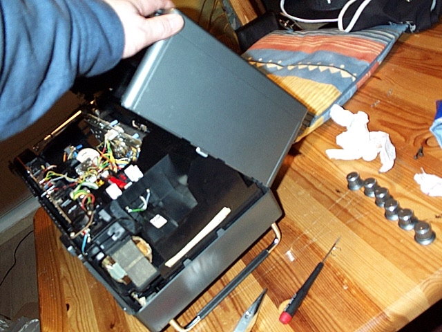
2. Place radio in face-down
position. (See pic)
3. All plastic catches
must align, Front part and back part of body. (See pic)
4. Bring them together
carefully and close back part of body downward to close body.
5. Make sure all sockets
on RF / IF board match to body. If necessary bring RF / IF board into correct
position by moving it with your fingertip. (See pic)
6. Enter 3 cross head
screws.
7. Push knobs back onto
correct shafts, ensuring the markers line up with the correct points on
the face of the radio when set to the ends of their movement, and you're
done!