
I.
INTRODUCTION
Today,
as we drive our automobiles, a great many of us, can enjoy the same comfort
levels that we are accustomed to at home and at work. With the turn of a button
or the slide of a lever, we make the seamless transition from heating to cooling
and back again without ever wondering how this change occurs. That is, unless
something goes awry.
Since
the advent of the automotive air conditioning system in the 1940's, many
vehicles have undergone extensive change. Improvements, such as computerized automatic
temperature control, which allow you to set the desired temperature and have the
system adjust automatically and improvements to overall durability, have added
complexity to today's modern air conditioning system. Unfortunately, the days of
"do-it-yourself" repair to these systems, is almost a thing of the
past.
Simply
put, repairs to your vehicle will cost you more. A basic knowledge of the automatic temperature control system
will allow you to make more informed decisions on your repair options,
furthermore, it will increase your purchase power when buying a vehicle.
Project
Description
As
more people grow accustomed to Automatic Temperature Control in vehicles they
are unaware of how they function. While
knowledge of a system design will not reduce repair or purchase costs, it will
provide a better understanding of the level of effort behind the comfort that is
received after an automobile’s temperature control is activated and set to a
desired temperature. This project
will provide you a front-end “web-based” representation of the high level
end-to-end Systems Engineering Development process · Planning and
Analysis · System Architecting · and System
Design · as it applies to an Automobile’s Automatic Temperature
Control. The fourth stage of this
process · Build and Test · will not be
explored in the analysis. The representation will be accomplished through
Unified Modeling Language (UML) elements and diagrams and the knowledge obtained
form discussions in the course.
II.
SYSTEM REQUIREMENTS
Creating the project concept and
generating the system requirements is the initial step in the design process.
Formal, organized requirements are a major factor to a well-designed
system. It provides for quick and
easy engineering changes to the design and rapid implementation for system
upgrades. Requirements are
generated based on the goals of the system “what it will do” and
corresponding situations, the users needs, system limitations and use case
modeling.
Stating the goal, a use case, and
determining all possible activities that could happen to achieve that goal is
use case modeling. This is a
repetitive process in which an initial use case model is established then a more
structured model is constructed from which the requirements are generated.
Below is a description of the two-
step process.
[1]
Determine Goals/Scenarios and Initial Use Case Modeling
·
Use Case and
Activity Diagrams
[2]
Structured Use Case Modeling
Goals
and Scenarios
At this point in the design
process only a high-level pictorial of what the system “will do” is known.
Several goals are established that are companied by one or many scenarios.
[1]
User will have control of power.
·
Scenario 1.1
Last temperature setting is displayed depending on button function.
·
Scenario 1.2
Temperature setting will extinguish when system is powered off.
[2]
The automatic temperature controller must be able to operator within any compact
to full sized road vehicle including Sport Utility Vehicles (SUV’s).
·
Scenario 2.1 the
user is able preset temperature.
·
Scenario 2.2 the
system must be durable to withstand vibration during on and off road travel.
·
Scenario 2.3 the
system must be temperature resistant.
[3]
System must control temperature
·
Scenario 3.1
System must maintain set temperature from user
[4]
Outside temperature reading
·
Scenario
4.1 Outside temperature shall be
displayed when is function invoked
[5]
System must be upgradeable.
·
Scenario 5.1 Car
seat heater feature may be added.
·
Scenario 5.2
Second or third control zone may be added.
[6]
The system must have quick reference to human factors interface
·
Scenario 6.1
Displays must be large enough for quick reading.
·
Scenario 6.2
Symbols must be used to assist with quick acknowledging of setting.
·
Scenario 6.3
Buttons shall be placed strategically to minimize reaching. An example would be often used buttons shall be placed closer
to the driver.
[7]
Display user output
·
Scenario 7.1
System shall display both inside and outside temperature to user
·
Scenario 7.2
User inputs shall be displayed on system display window.
Determine
Actors
By definition an actor is an
external participate in the use case model.
Identified below are the three external participates that interface with
the Automobile’s Automatic Temperature Control.
[1]
User – the driver or passenger of the vehicle
[2]
Ambient Temperature – the outside temperature plays an important role in the
system. It acts as a sensor for the
user.
[3]
Power Source – The automatic temperature control is powered by the vehicles
battery/engine.
Initial
Use Case Diagram
The initial use case diagram
depicts the high level interface between the use cases and the actors within the
Automatic Temperature Control system. The
rectangular box represents the system, the use cases are within the system
represented by ovals and the actors (external participates) are outside the
rectangular box represented as stick figures.

The User is the primary actor on
the system. The User activates the
power and the cabin temperature control. The
Use reads the outside temperature control panel and depresses the interface to
determine the desire temperature needed within the vehicle.
This particular actor would determine the chose of system upgrade if
desired. This actor would read the
output of the system.
Defining
Use Cases
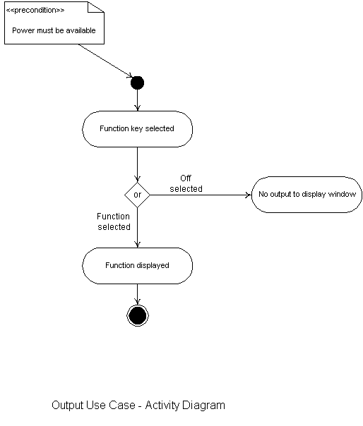
The seven use cases depicted in
the Initial Use Case Diagram are explained in detail below.
All primary actors for each case are presented along with the case
description, pre/ post conditions, the flow of events and assumptions. To show a
graphical representation of each use case, Activity Diagrams have been
constructed.
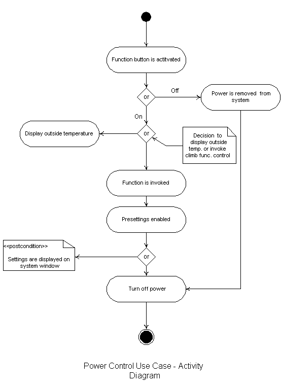
[1]
Power Control
Primary
Actors: User and Power Source
Description:
User will have control of the power to activate the temperature.
Preconditions:
None
Flow
of Events:
1.
User
invokes function and pre-settings are enabled
2.
User
can read inside temperature if desired
3.
Power
is activated until user turns off power
Post
Conditions: Setting are displayed on system window
Assumptions:
None
[2]
Cabin Temperature Control
Primary Actors: User and Power Source
Description:
The user is able preset
temperature. The system must be
durable to withstand vibration during on and off road travel. The system must be temperature resistant.
Preconditions:
Power Source must be activated
Flow
of Events:
1.
Read
pre-setting conditions
2.
Read
and adjust the temperature sensors and settings.
3.
Read
function key
4.
Adjust
Vent
5.
Turn
power off
Post Conditions: None
Alternative
Flow of Events: None
Assumptions:
None

[3]
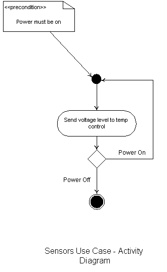
Sensors
Primary
Actors: Power Source and Ambient Temperature
Description:
System
must maintain set temperature from user
Preconditions:
Power Source must be on
Flow
of Events:
1.
Voltage level is sent to temperature control
2.
Power is turned off
Post
Conditions: None
Alternative
Flow of Events: None
Assumptions:
None
[4]
Outside Temperature Reading
Primary
Actors: User and Power Source
Description:
Outside temperature shall be displayed when is function invoked
Flow
of Events:
1. User invokes function and
pre-settings are enabled
2.
User
can read outside temperature if desired
3.
Power is activated until user turns off power
Post Conditions: Settings are displayed on
system window
Alternative
Flow of Events: None
Assumptions:
None
Activity
Diagram: Same as Power Control Use Case - Diagram
[5]
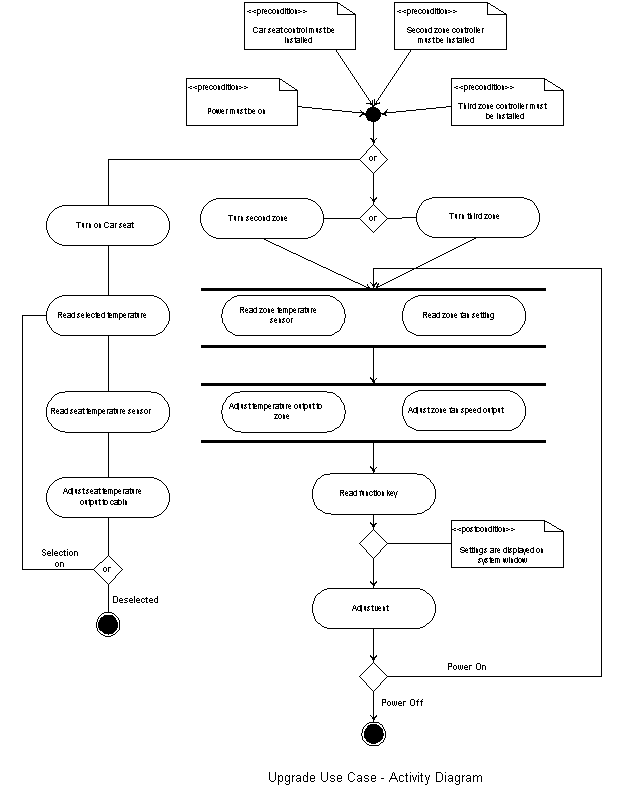
Upgrades
Primary
Actors: User and Power Source
Description:
Car seat heater feature
may be added to driver and passenger seats. Second or third control zone may be
added.
Preconditions:
Car seat control must be installed, second and or third zone controller must be
installed, and power must be on.
Flow
of Events:
1.
Heating zone is turned on
2.
User
reads selected temperature
3.
User
reads seat temperature senor
4.
User
Adjusts seat temperature
5.
Zone
heating is turned off
Post
Conditions: Settings are displayed on system window
Alternative
Flow of Events: None
Assumptions:
None
[6]
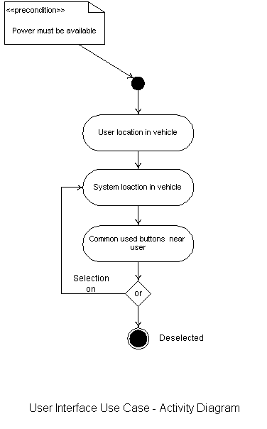
Interface
Primary
Actors: User and Power Source
Description:
Displays must be large
enough for quick reading and symbols must be used to assist with quick
acknowledgment of setting.
Preconditions:
Power must be available
Flow
of Events:
1.
User
is located in vehicle
2.
System
must be located in vehicle
3.
Commonly
used buttons must be near user
4.
User
deselects interface
Post
Conditions: None
Alternative
Flow of Events: None
Assumptions:
None
[7]
Output
Primary
Actors: User and Power Source
Description: System shall display both inside and outside temperature to
user and User inputs shall be displayed on system display window.
Preconditions:
Power must be available
Flow
of Events:
1.
Function
key is selected
2.
Function
key displays out temperature
Post Conditions: None
Alternative
Flow of Events: None
Assumptions:
None
Formal
Requirements
At this stage in the Planning and
Analysis stage of the Development Design we have described all the use cases,
goals and their respective scenarios. With this information we can write the
formal requirements and structure them by requirement category; Performance,
User Interface, and Power Source.
1. Performance Requirements
1.1
System
shall display both inside and outside temperatures
1.2
User
inputs shall be displayed on system display window
1.3
System
must be durable to withstand vibration during on and off road conditions
1.4
System
must be temperature resistant
1.5 System should be easily upgraded to accommodate heated car seats
1.6 System shall accommodate Zoned controls
Sources: Use Case 2, 5 and 7 ·
Goal 2, 5 and 7 ·
Scenario 2.2, 2.3, 5.1, 5.2,7.1 and 7.2
2. User Interface Requirements
2.1
Displays
must be large enough for quick and easy reading
2.2
Often
used buttons shall be placed strategically to minimize reaching.
2.3
Symbols
must be used to assist with quick reading
2.4
User
should have the ability to preset temperature
Sources: Use Case 2 and 6 ·
Goal 2 and 6 ·
Scenario 2.1, 6.1, 6.2 and 6.3
3. Power Requirements
3.1 When system power is off the temperature setting should be
extinguished
3.2 When power is activated setting is displayed depending on button function
depressed.
Sources: Use Case 1 ·
Goal 1 ·
Scenario 1.1 and 1.2
Structured
Use Case Modeling
The initial use case modeling
procedures are the baseline to determine the Structured Use Case Model that the
system design will be based upon. The
initial use cases are investigated to determine which ones need further
clarification to assistance in the development of the logical design. Goals 1
and 4 need to be consolidated to provide a more structured depicts of the
systems use cases. From which the
Structured Use Case Model is constructed indicating six use cases.
Goals
and Scenarios
[1]
The user will have control of power features of the system.
This includes the display of the outside temperature reading that are
received form the outside sensor.
·
Scenario 1.1
Last temperature setting is displayed depending on button function.
·
Scenario 1.2 Temperature setting will extinguish when system
is powered off.
·
Scenario
1.3 outside temperature shall be displayed when user invokes function.
The outside sensor should indicate the ambient temperature only when the
user depresses display function.

The
new use case diagram has been organized to reflect six use cases not our
original seven. The use cases have
been extended to other use cases to indicate the behaviors that are required
between the two to complete a requirement.
The behaviors of the use cases are investigated in detailed in the System
Architecting phase of the development cycle.
III.
SYSTEM BEHAVIOR
The second phase of the end-to-end
engineering design cycle is System Architecting.
During this cycle the question of “How will the accomplish the
goals?” are answered. By definition, An architecture framework provides common
definition, data and references, and describes a set of products providing views
of the system structure. The components and subcomponents of the systems are
investigated to determine their behavior and how they will be mapped on the
system structure.
Subsystems
Temperature Control – provides
the user control of the vents, transducers, cabinet sensors and the overall heat
and Air Conditioning power.
Power
System –provides user control of the power source and converter.
Output – this system acts as the interface between the user and the system.
Function
Keys – this feature provides the user ability to control the temperature and
location of vents
Monitor
Cabin Temperature – this feature monitors the temperature within the vehicle .
Display
Outside Temperature – this system provides visual human interaction with the
user. It displays the
ambient temperature outside of the vehicle
Component
Interaction
The relationship between the
subsystem and the use cases are displayed in the Interaction Diagram below.
This diagram represents a many to many relationship of the subsystems to
the use cases. The actors are shown
elevated above the use cases with a one to many relationships as depicted in the
organized use case diagram.
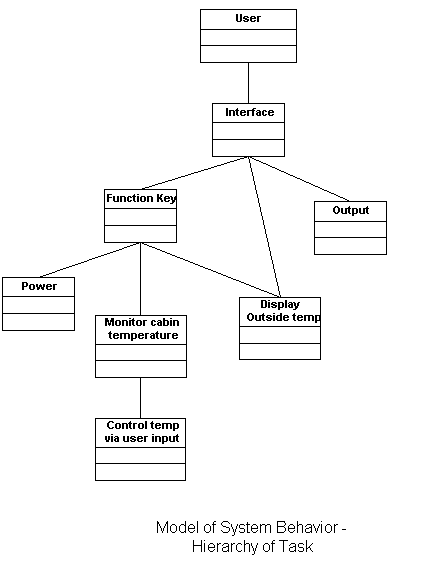
The
system behavior is further depicted through a graphically representation of the
hierarchy of task. In the below
figure the User is depicted as the primary actor on the system that interfaces
with the Function Key and the Output. The
Function Keys concurrently interact with the Power, Monitor Cabin Temperature,
and Display Outside Temp. Furthermore,
the Monitor Cabin Temperature interacts with the Control Temperature.

IV.
SYSTEM STRUCTURE
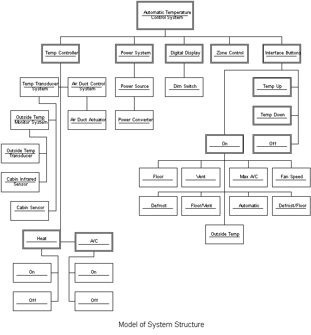
The system behavior as it relates
to the system structure is identified in the System Architecting phase.
The way in which the behavior is mapped onto the system structure needs
to be clarified for the purpose of the design phase.
Knowing this prior to the design of the system one will have a clear
understanding of all the parts of the system and how they relate to one another.
A high-level model of the system structure is depicted below.

From the model of system structure
we can map the behaviors of the system onto the structure.
Previously we identified all the subsystems, now we align them within the
Automatic Temperature Control System with the User as the primary actor on the
system. The relations are the directional arrows depict relationships.
Once a full understanding of the
relationship of how the system behavior relates to the structure the design can
be clearly stated and understood. Below,
a detailed mapping is shown.

V.
LOGICAL DESIGN
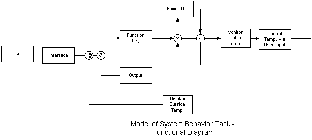
The third phase of the end-to-end
development cycle is System Design. During
this phase the actual design is built and the question of “how will the system
work?” is answered. All the
behavioral and structure concerns have been addressed by this stage and a
representation of the design is done in a matter that is simple to understand.
Below is a high – level design of the system provided in the a
Functional Flow Diagram.

|
Source |
Destination |
||
|
Use Case |
Scenario |
Req. No. |
Description |
|
Use will have control of power |
Last temperature setting is displayed depending on
button function |
||
|
Temperature setting will extinguish when system is
powered off |
|||
|
The automatic temperature control must be able to
operator within any compact to full sized vehicle including an SUV |
The user is able preset temperature |
||
|
The system must be durable to withstand vibration
during on and off road travel |
|||
|
The system must be temperature resistant |
|||
|
System must control temperature |
|
System must maintain set temperature |
|
|
Outside Temperature Reading |
Outside temperature shall be displayed when function
is invoked |
||
|
System must be upgradeable |
Car seat heater feature may be added |
||
|
Second or third control zone may be added |
|||
|
System must have quick reference human factors
interface |
Displays must be large enough for quick reading |
||
|
Symbols must be used to assist with quick
acknowledging of setting |
|||
|
Buttons shall be placed strategically to minimize
reaching |
|||
|
Display user output |
System shall display both inside and outside
temperature to user |
||
|
User inputs shall be displayed on system display
window |
|||
Traceability Matrix
VI.
EVALUATION OF SYSTEM DESIGN
ALTERNATIVES
Trade-off analysis is coupled with
the logical and physical designs of a systems design project.
This analysis is accomplished after requirements have been formalized and
documented, which is closer to the close of the project.
During the Planning and Analysis
phase of this project it was determined that the system would be designed to
accompany upgrades on an optional basis. The
upgrades of heated car seats not only for the driver and passenger but two
additional zones. In determining
the need the demand for the upgrades and ranking of the alternatives a Decision
Matrix, the Laplace, Maximin, Maximax Criterions and Regret Tables are utilized
to evaluate the design alternatives.
|
Demand
for Upgrade |
|||
|
Upgrade Order for Heated Seats |
90,000 |
20,000 |
28,000 |
|
10,000 |
230K |
- |
2,130K |
|
20,00 |
-440K |
660,000 |
- |
|
30,000 |
-1,110K |
- |
-790K |
Sell
Price
Unit Cost
Upgrade A = regular system + seat
heater
$ 500.00
$ 415.00
Upgrade B = Upgrade A + zone 1
control
$ 800.00
$600.00
Upgrade C = Upgrade B + zone 2
control
$ 1,000.00
$708.00
Sell
Price
Unit Cost
Seat heater
$200.00
$167
Seat heater
+ zone 1
$500.00
$375
Seat heater + zone 1 + zone 2
$700.00
$496
Upgrades
10K
9000(200-167)-((167-100)(10,000-9000)
= 230K
9000 (200-167) – ((167-100)
(20,000 –9000) = -440K
9000(200-167) –((167-100)(30,000
– 9000) = -1,110K
Upgrades
20K
20,000(200-167)-((167-100)(10,00-20,000)
= 0
20,000(200-167)-((167
–100)(20,000-20,000) = 660K
20,000(200-167)-167-100)(30,000-20,000)
= 0
Upgrades
28K
28,000(200-167)-((167-100)(10,00-28,000)
= 2,130K
28,000(200-167)-((167
–100)(20,000-28,000) = 0
28,000(200-167)-167-100)(30,000-28,000)
= -790K
Decision Matrix
for Upgrade
|
Upgrades |
10,000 |
20,000 |
28,000 |
|
10,000 Upgrade A |
849,835 |
3,335,000 |
5,350,000 |
|
20,00 Upgrade B |
1,999,800 |
4,000,000 |
9,200,000 |
|
30,000 Upgrade C |
2,920,000 |
7,920,000 |
5,617,800 |
Upgrades
10K
Upgrade A
10K(500-415) – (415-250)(10K-10K) =
849,835
Upgrade B
10K(800-600) – (600-400)(10K-10K) =
1,999,800
Upgrade C
10K(1000-708) – (708-500)(10K-10K) = 2,920,000
Upgrades
20K
Upgrade A
20K(500-415) – (415-250)(10K-10K) = 3,335,000
Upgrade B
20K(800-600) – (600-400)(10K-10K) = 4,000,000
Upgrade C
20K(1000-708) – (708-500)(10K-10K) = 7,920,000
Upgrade
28K
Upgrade A
28K(500-415) – (415-250)(10K -28K) = 5,350,000
Upgrade B
28K(800-600) – (600-400)(10K -28K) =9,200,000
Upgrade C
28K(1000-708) – (708-500)(10K-28K) = 5,617,800
Laplace
Criterion
Upgrade A (10K) = (849,835 –
3,350,000 + 5,350,000)/3 = $3,183,278
Upgrade B (10K) = (1,999,800 +
4,000,000 + 9,200,000)/3 = $5,066,600
Upgrade C (10K)
= (2,920,000 + 7,920,000 + 5,617,800)/3 = $5,485,933
To
determine the greatest profit for lowest order the Maximin Criterion resulted in
Upgrade C
To
determine the greatest profit for greatest order the Maximax Criterion resulted
in Updated B
Regret Table
|
Upgrades |
10,000 |
20,000 |
28,000 |
|
10,000 Upgrade A |
2,070,165 |
4,570,000 |
3,850,000 |
|
20,00 Upgrade B |
920,000 |
3,920,000 |
- |
|
30,000 Upgrade C |
- |
- |
5,617,800 |
Maximin
= Upgrade B
Maximax
= Upgrade C
VII.
CONCLUSION
A recommendation to further the
research of this project would be to expand the system options of the heated car
seats. Future students could
evaluate the design of the three zones and retrofit their analysis into this
project. Utilizing methods of reuse
would make for an interesting project.
While researching this project it
was beneficial for us to conduct tradeoff analysis using methods other then the
Analytical Hierarchy Process (AHP). As
a result of choosing the methods used for tradeoff analysis, a greater
understanding of ranking system alternatives was obtained.
The difficult part of this project was formulating the right question for
the problem and answering the question appropriately trying to expand the use
case models that were initially established.
The knowledge base on this project
made it easy to reach project completion in a timely fashion with agreed upon
roles and responsibilities.
VIII. REFERENCES
Lecture Notes for ENSE 621 and ENMP 641 System Engineering Principals August
2001: M. A Austin and B.A. Frankbitt, Institute of Systems Research,
University of Maryland, College Park, MD 20742.
Lecture Notes for ENSE 622/ENPM 642: Systems Engineering Requirements,
Design and Trade-Off Analysis, March, 2002: Mark Austin, Institute of
Systems Research, University of Maryland, College Park, MD 20742.