Current Direction Switching |
|
The Assignment: Take two approximately 1.0 m pieces of wire, and solder two LED's in series with them, so that positive current turns on the red and negative current turns on the green LED. Then build circuitry involving two TTL inputs such that it is possible to turn on one or the other or neither LED. Use whatever components you need. |
|
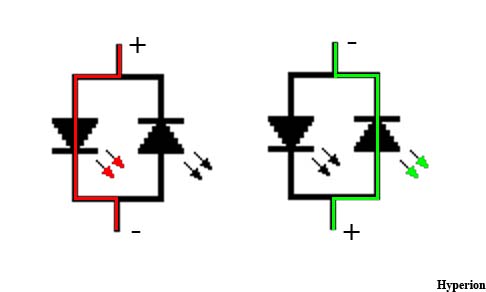
The Setup: The following diagram depicts the orientation and connection of the LED's. Since LED's are Light Emitting Diodes, light will only be emitted when the diode is forward biased. This means that connecting the LED's in parallel with each other while reversing their polarity ensures that one diode is forward biased while the other is reverse biased. When the wires are energized, one of the LED's will always be lit, indicating the direction of current flow. |
 |
| To control the direction of current flow through our test wires, a transistor H-Bridge was constructed. An H-Bridge consists of 2 NPN and 2 PNP transistors. These transistors are used as switches arranged in the following orientation. Changing which switches are open and closed changes the direction of current flow through the load. |
 Image Obtained at http://www.barello.net/Papers/H-Bridge.pdf |
Here is a schematic diagram of an H-Bridge. The resistors are there to limit the current allowed to flow through the base of the transistors allowing inputs A and B to be used as TTL. If input A and B are not connected, then A and B will float low and no current flows through the LED's. All the switches are open. If we apply a 5V signal to input A (TTL High), then two of the four switches will close and current will be allowed to flow in one direction through the LED'S. If we apply 5V signal to input B (TTL High) and remove the signal from A (TTL Low), then the other two of the four switches will be closed and current will be allowed to flow in the other direction through the LED's. |
 Imaged obtained at: http://www.solarbotics.net/library/circuits/driver_4varHbridge.html Modified By: Hyperion |
| I did make one interesting observation. When Inputs A and B are both low all switches should be open, however, it appears there is some leakage of current. The Idea of transistors being perfect on/off switches seems to be inaccurate. This leakage of current can lead to very warm transistors. I recommend selecting a transistor with a current rating capable of passing a good deal more then your load and leakage currents combined. The use of a heat sink might also be a good idea for sustained operation. |