Computers come in all types and sizes. There are primarily two main sizes of computers. They are:
The portable computer comes in various sizes and is referred to as laptops, notebooks, and hand-held computers. These generally denote different sizes, the laptop being the largest, and the hand-held is the smallest size. This document will mainly talk about the desktop computer although portable computer issues are also discussed in various areas.
Computers are made of the following basic components:
There are two basic styles of cases the computer may come assembled in. They are basically tower and desktop style cases. Desktop style is in the shape of a rectangular box, that sets flat on a desk. Usually the computer monitor is placed on top of it. A tower case, looks similar to a tower as the name says. These computers will be placed off to the side of the keyboard and monitor. The tower case is the most popular style of desktop computer today. It is also recommended by some microprocessor manufacturers since it can be designed for better heat dissipation. Tower cases come in several sizes which are:
Looking at the front of your computer, you see the front panel:
The exact locations of many of these items vary somewhat from computer to computer, but the overall layout is generally the same. Types of cases come to fit AT and ATX sizes. If you want a modern computer, you will want, or should have an ATX case. The AT or ATX version refers to the type of motherboard the case is designed to fit. The AT case is for the old type of motherboards such as for the 80486 microprocessor based computers.
The back panel includes two power connectors. One is to connect your computer to the wall outlet, and the other can be used to connect the monitor power to operate from the socket on the back of the case. Usually the power connector for the monitor is not used since many use a power strip or a surge protector to control the power to all devices.
The keyboard and mouse connectors are both normally PS2 connectors on new computers. There are two sizes of PS2 connectors, Normally with today's equipment you will want the smaller PS2 connector on your keyboard. Mice don't come with the larger PS2 connector. There are adapters made to allow smaller connectors to adjust to a larger sockets and vice-versa. A PS2 connector is a round connector with 6 pins and a plastic key. The keyboard always uses the PS2 connector, however the mouse may be a serial mouse and may plug into the serial cable on your computer. With modern computers, normally a PS2 mouse will be used.
Near the keyboard and mouse connectors is normally a connector for a parallel printer. This is what is called a parallel device, meaning that more than one line carries data in one direction at a time. This is the connector you will plug your parallel printer into. See your computers motherboard or owner's manual for exact placement of these connectors.
Usually a little below the parallel printer connector are two serial connectors. There are two types of serial connectors, which are called DB9 and DB25. One type, DB9 contains 9 pins or sockets and the other contains 25 pins or sockets. You may have any combination of the 9 or 25 pin connectors. Also some are female style connectors, and others are male. You will need to make sure your connectors match for their given types. The serial cables are normally used to connect a serial mouse, an external modem, or some other device to your computer.
Below the parallel and serial connectors are a series of slots which are covered by a metal plate. This is where additional cards are plugged into your system. These cards are usually a video card, a sound card, internal modem, and one or more network cards. Your monitor connector would plug into a connector on your video card, and your speakers will plug into a connector on your sound card. See your sound card and video card manual for exact placement of these connectors on the card. These cards are plugged into the motherboard and you must open your case up to remove or add one of these cards.
Warning! Before deciding to open your computer case and touch or remove any parts inside, you should be aware that your body can contain static electricity that may be discharged to the circuits inside your computer. A static discharge can damage or ruin your computer. Therefore prior to doing any work inside your computer, you should get a grounding strap. A grounding strap can be attached to one of your wrists and be plugged into the wall (if it is the type made for a wall outlet). If you don't have the ground strap made for the wall outlet, you may need to attach your ground strap to a cold water pipe. A ground strap grounds your body using the earth ground in the wall outlet or from a cold water pipe. A grounding strap should cost less than twenty dollars and should be available at an electrical equipment store. You should always wear a ground strap when working inside your computer case. Especially when working with the microprocessor, memory, motherboard, or other plug in boards.
Warning! Hazard! Prior to opening your computer case, be sure it is turned off and unplugged. 110 volts can cause injury or death! Also working on your computer while it is plugged in can damage or destroy it.
To open the computer case, depending on the type of case you may need to follow one of the following sets of instructions.
Once you have opened the case, lay it on its side so you can look at the inside components. You should see some variation of the following picture.
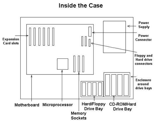
In the picture, the front of the computer is at the bottom and the rear is at the top. At the front (bottom of the picture) are normally two metal bays made to enclose hard drives, floppy drives, and CD-ROM drives. There is a 5.25 inch and a 3.5 inch set of bays. Most hard drives will mount into the smaller 3.5 inch bays with the CD-ROMS mounting in the 5.25 inch bays. The hard floppy, and CD-ROM drives are mounted to their enclosures with screws on their left and right sides. The power supply is on the top right side of the picture which when the computer is in its normal standing position is the top rear. At this location it will draw the warm air that naturally rises to the top of the case to the outside.
Between the hard, floppy, and CD-ROM drive bays you will see some thin flat grey cables going to the floppy and hard drive connectors on the motherboard. These are data/control cables used by the system to control the drives and get and send data from and to them. On one side of the grey cable should be a red stripe going along the cable. This red stripe should always be placed on the pin 1 side of the connector. You will need to look closely at the connectors on your hard and floppy drives to determine which is the pin 1 side or read your manual. On hard drives and most CD-ROMs pin 1 is on the side closest to the power supply connector.
Cables running between the power supply are colored black, red, and yellow. There is one going to each hard drive, floppy drive, CD-ROM drive and any other drive the system is using such as a mass storage device. There is also a multicolored power supply cable with about 12 wires going between the power supply and the motherboard. The wires are colored black, red, yellow, orange, and there is one that is blue. The connector on this cable should be keyed so it cannot be inserted the wrong way. Also some of the data cables are keyed, but others are not. It varies a little from system to system.
The primary rating on the power supply that you should be concerned about is wattage. Most are standard in the range from 230 through 300 watts. I recommend 250 watts for most standard systems today. If you are buying a high powered system with a microprocessor that uses a lot of power such as an AMD Athlon, you will need to buy a case that has a power supply capable of providing 300 watts.
The following sections talk about the motherboard and associated components such as memory, the microprocessor, and the expansion cards.
Yes, the motherboard is the mother of all boards on your computer. The motherboard may have a form factor of AT or ATX. We recommend you use ATX motherboards with ATX cases since this is the newer alternative and most modern microprocessors run on ATX motherboards. The motherboard holds the microprocessor, the memory, and several card slots. The memory may be SIMM sockets or DIMM sockets. The current standard is DIMM socketed memory. This is usually 168 pin 3 volt unbuffered synchronous DRAM memory. PC100 or PC133 memory is the current memory of choice. Most boards have 3 or 4 memory slots, which may, depending on the size of DIMM used, allow up or beyond 1 Gb total system memory. Most boards commonly allow 384 to 512 Mb of system RAM.
The card slots are used to put additional cards such as video cards, sound cards, internal modems, or network cards into. Some motherboards today include video and sound without the addition of a extra card. These cards slots today are mostly PCI type card slots. When talking about cards that are plugged into a PC you are talking about the expansion bus. The expansion bus is a means of a microprocessor extending its communication ability further into the outside world. It is a data exchange means between add on cards and the microprocessor and the motherboard. There have been several types of expansion buses.
The current popular expansion bus is the PCI (Peripheral Component Interconnect) bus for all cards except the graphics cards. For graphics cards, the bus of choice is AGP. Most motherboards today have one AGP slot and several PCI slots. Your expansion cards will plug into these card slots. Be sure you get cards that match the available type of slots on your motherboard.
As PC technology grew, eventually the access speed of the memory could no longer keep pace with the increased speed of the microprocessors. At this point, an I/O cache was placed on the microprocessor to be a buffer between the external memory on the motherboard and the internal processor registers. The memory was set to run at a different "side bus" speed which is some fraction of the microprocessor speed. Therefore when the speed of the microprocessor is set, it is set to some multiple of the side bus speed. In the case of a 500Mhz processor and 100Mhz PC100 capable memory, that multiple is 5. Sometimes this multiple and the sidebus frequency is set using jumpers on the motherboard, or it may be set with auto detection and the BIOS. You will need to consult your motherboard manual to determine how to set these parameters.
Other items on your motherboard that you should be aware of are the small pin connectors that are used to connect the following controls and indicatory to your motherboard.
You will need to consult your motherboard manual to see which connectors are used for which item and how to hook them up. There should be a bundle of cables near the front of the case (inside) which have labels on the connectors for these items.
One issue that will affect the operation of the motherboard is the chipset it uses and its BIOS it uses. The chipset is used to control the interface between the microprocessor and most of the devices and memory on the computer. The chipset used can have a significant affect on the performance of your system as can the overall design of the motherboard. The way to determine the best chipsets and motherboards is to read reviews and articles at various technical websites.
Your system's BIOS is a computer program that allows your system to begin running and provides a small library fo function that your system will use to interface to various devices such as your hard drive. Some BIOS programs can limit the location on your hard drive where you can install bootable operating systems. The BIOS resides in a chip on the motherboard called a ROM chip. Usually part of this ROM can be reset or re programmed with updates. ROM that can be electrically re-written this way is called "flash" ROM.
The microprocessor is the center of your computer. It processes instructions and communicates with outside devices, controlling most of the operation of the computer. The microprocessor usually has a large heat sink attached to it. Some microprocessors come in a package with a heat sink and a fan included as a part of the package. Other microprocessors require you to install the heat sink and fan separately. This is not a difficult problem, but can be a bit daunting when the buyer wants to make sure they get the correct parts to fit their microprocessor. Also the buyer needs to make sure they will get the motherboard that their microprocessor will work with. This section will explain some of the differences in microprocessors and ways to be sure your parts match.
The mounting method refers to the type of connection the microprocessor makes with the motherboard. The following table lists the various mounting packages and some of the well known microprocessors that are mounted for that package.
The Socket 7 processors are becoming less popular. We recommend socket 370, through slot A microprocessors at the current time. The prices on Socket 370 microprocessors are currently very low considering the performance of the systems. I recently bought a Celeron 500Mhz microprocessor with 66Mhz sidebus for under $120 with a motherboard for $84. When buying a microprocessor, make sure you get the type of socket you think since some processors are made for different sockets such as the Celeron. Be sure of one of the following.
It would be no fun to get a Slot 1 motherboard and a socket 370 Microprocessor.
Being sure you get the correct heat sink and fan for your microprocessor can be a bit daunting. Who wants to get a $300 microprocessor, and risk it with an incorrect mounting of a heatsink or fan? Who wants to find out that they have purchased the wrong heatsink for their processor and spend days or weeks trying to sort it out? My solution is to purchase the microprocessor with the heatsink in the same package. Usually you get a better warranty and return policy this way and you don't need to worry about whether the two are compatible. I do not believe you can save enough money buying the heatsink and fan from anyone other then the vendor selling the microprocessor because of the time it takes for the additional research required and the potential trouble. The best solution to this problem is simply to buy a slot1, slot II or slot A microprocessor with the package that includes the fan and heatsink. These would be one of the Pentium II, Pentium III, Athlon, or Xeon packages. All that is required in this case is to slide the microprocessor carefully into its slot. With the exception of processors such as the Athlon which have a larger heat sink, requiring an extra plastic clip mechanism to help stabilize the heatsink, it is easier to install one of these processors than it is to install the computer's RAM memory or a hard drive.
Memory chips are called DIPs which stands for Dual Inline Packages. They are black chips with pins on both sides. Some say they look like black bugs. To make memory installation easier than it was in the past, these DIP chips were places on modules. There are two main module types that memory comes packaged on today.
To install these packages, you press them into the socket on the motherboard and latch them in with a plastic latch on both sides. Normally as the memory module is pressed into place the latch will automatically latch the module in place. This is the essential knowledge required to understand enough to buy and install memory on your motherboard. The following sections give further technical details.
DRAM memory is is accessed in chunks called cells. Every cell contains a certain number of bits or bytes. A row, column scheme is used to specify the section being accessed. The cells are arranged similar to the following table.
|
ROW 1, COL 1 |
ROW 1, COL 2 |
ROW 1, COL 3 |
ROW 1, COL 4 |
|
ROW 2, COL 1 |
ROW 2, COL 2 |
ROW 2, COL 3 |
ROW 2, COL 4 |
|
ROW 3, COL 1 |
ROW 3, COL 2 |
ROW 3, COL 3 |
ROW 3, COL 4 |
|
ROW 4, COL 1 |
ROW 4, COL 2 |
ROW 4, COL 3 |
ROW 4, COL 4 |
When the DRAM is accessed, the row, then the column address is specified. A page in memory is considered to be the memory available in the row.
The term DRAM stands for Dynamic Random Access Memory. There are three common types of DRAM today.
Another new type of DRAM is called RDRAM developed by Rambus, Inc. It uses a high bandwidth channel to transmit data at very high rates. It attempts to eliminate the time it takes to access memory. Synclink DRAM (SLDRAM) competes with RDRAM and uses 16 bank architecture rather than 4 along with other performance enhancing improvements.
 Cache
memory is special memory that operates much faster than SDRAM memory. It is also
more expensive. It would be impractical to use this memory for the entire system
both for reasons of expense and physical board and bus channel design
requirements. Cache memory lies between the microprocessor and the system RAM.
It is used as a buffer to reduce the time of memory access. There are two levels
to this memory
Cache
memory is special memory that operates much faster than SDRAM memory. It is also
more expensive. It would be impractical to use this memory for the entire system
both for reasons of expense and physical board and bus channel design
requirements. Cache memory lies between the microprocessor and the system RAM.
It is used as a buffer to reduce the time of memory access. There are two levels
to this memory 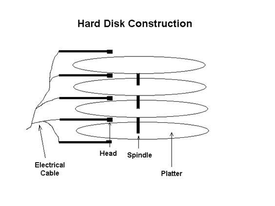 called
L1 (level 1) and L2 (level 2). The level 1 memory is a part of the
microprocessor, and the level 2 memory is just outside the microprocessor.
called
L1 (level 1) and L2 (level 2). The level 1 memory is a part of the
microprocessor, and the level 2 memory is just outside the microprocessor.
Hard drives consist of a series of round metal plates called platters, also called cylinders. They are coated with an electromagnetic material which can support magnetic states that are capable of being electrically altered. This means some type of electrical signal can alter the magnetic polarization of various areas of the plates. The state of these polarized areas can also be sensed. Each platter can hold large amounts of data. There are several platters mounted on a hard drive. Between each platter is a head which is used to sense and modify the states of the platter. There are two heads on each platter.
Each platter has data stored on it in a specific pattern for read and write access. The data is organized into tracks which are rings around the platter. The distance the head moves into the platter will determine which track is read. A sector is a section of data in the cylinder. Different hard drives have different numbers of sectors, tracks, and platters. The total storage space on the hard drive is traditionally equal to:
Sector size times sectors/track times tracks/cylinder times the number of cylinders.
With more modern drives, however, to increase storage space, some drives have more sectors on the outer tracks than the inner tracks. This is because there is more physical room for data on the outer tracks. Therefore this method of calculating hard drive capacity may not be effective in the future.

The storage capacity of most CD-ROMs is about 650Mb of data. Originally CD-ROMS were read only devices, but now read/write technology has been developed.
Many CD-ROMs are interface to the computer using the ATAPI interface. This is ATA Packet Interface which is a IDE interface. This is designed for extra drives like CD-ROM's and tape drives that connect to an ATA connector. The ATAPI interface is the standard interface for IDE controlled CD-ROMS. If your CD-ROM uses an a ATAPI interface, it should be supported by all available software. If you are using a SCSI controller, you should probably use a SCSI CD-ROM. There are two primary types of CD-ROMs today.
These are primarily available as an internally mounted drive, but can also be purchased as an external device. There are some CD-ROM drives that interface through the parallel printer port.
The primary performance concern of CD-ROM drives is their speed. Speeds are expressed in terms of 1X, 2X, 4X, which is the number of times the drive is than the standard CD-ROM reader. Of the read only type, speeds have exceeded 50X. CD-ROMS of up to 40X speeds and beyond can be purchased today for a reasonably low price.
The read/write types of CD-ROM speeds are expressed with three values. They are read, write, and rewrite. Current speeds of these devices are 32X, 10X, 4X. Currently 32X by 8X by 4X are priced reasonably at around $220. This compares to a 40X read CD-ROM drive at around $30-40. Therefore we recommend you do not rely upon your read/write CD-ROM drive for reading normal CDs especially where playing games in concerned. You could wear out your expensive CD-ROM performing read operations which costs a great deal more than a read only CD-ROM!
Monitors are used to view your data on a computer. The characteristics of your monitor are very important for your system performance since the quality of your video will significantly affect your computing experience.
Most monitors today consist of a picture tube and electronic control circuitry which are used to transfer the signal to the screen. There are some monitors that do not use a picture tube, but use electronics to display information. These monitors are more expensive and are not usually very large, but are primarily used for smaller computers such as notebooks and laptop computers. We will not discuss the flat video displays in this section at this point in time.
The primary and most expensive component in a standard monitor is its picture tube. The most important characteristics of a monitor generally refer to picture tube specifications although other circuitry can also be important in providing picture clarity. A picture tube is basically a large vacuum tube with a phosphorescent coating on the front of it. At the back of the picture tube is a large electron gun ( actually 3 guns ) which shoot(s) electrons onto the phosphorescent coating at the front of the tube. When the electrons strike the coating, the coating glows. The coating provides the primary colors which are green, red, and blue. These component colors and their combinations can be used to make every other possible color combination. There is other circuitry which works with the gun to direct the electron gun to the proper color at the correct time, and to direct the gun to the correct location on the screen depending on the phase of the video signal that is being sent to the monitor. There is magnetic circuitry which is used to bend the electron beam to strike the appropriate area on the screen. This is referred to as deflection.

The yoke is an electromagnetic coil used to guide the beam to its intended location. The color pattern on the phosphorous appears like the three colored circles shown on the left side of the drawing below. There are many of these color patterns on the screen. The closer the groups of
these three patterns are, the better the resolution of the monitor can be. Monitor resolutions refers to the number of lines per inch that can be seen on the screen. It is rated in vertical (up and down the screen) and horizontal (left and right) terms.
Some of the most important specifications on the monitor are:
Different manufacturers and vendors rate dot pitch different ways. There are actually three characteristics of dot pitch. They are:
As you can see depending on how the dot pitch is measured, you may get different numbers. You will need to carefully check manufacturer's specifications to be sure the monitor you buy has the spacing you think it has. I was once interested in purchasing a monitor that according to the article I read had a dot pitch spacing of .22 mm. When I looked at the vendor website for that model, it stated .26 mm. I went to the manufacturer's website and it stated .22mm horizontal and .22mm vertical. So I did the math.
.22 squared +.22 squared = .26 squared
If you would really like to get any use on your computer, you would probably like a keyboard and a mouse.
Keyboards can range in cost from about $10 to $100. I generally stay with less expensive keyboards, but I try to avoid buying a keyboard with the large type PS/2 connector as mentioned in an earlier section. There are keyboards with a different feel or sound when key pressing is done. Some people are particular about the feel and sound. If you are, you may want to spend a little more for your keyboard. You may even want to buy it from a retail store so you can test the feel of it. There are special keyboards with extra functions on them for such things as surfing the internet.
The mouse interface of choice is the PS/2 interface rather than the older serial interface. Using a PS/2 interface will not require the use of a serial port on your computer. There are a few types of mice available. The main choices are between:
The choice of two or three buttons depends on your preference and whether the software you run on your computer will support a three button mouse. If it does not support three buttons, it just means that you will not be able to use the third button. Many mice today have a sprocket wheel in the center which will allow the user to scroll up and down documents on the screen by turning the wheel. Also some mice are "ergonomic". I'm sure I misspelled that word.