

Here are some of the many projects that I've built using components
made by Meccano, Erector, Ashok (high quality replica parts), etc.
|
|
|
| Tower Crane | Trebuchet | Cars |
This is an ongoing project that I work on from time to time.It stands
just over 6 feet tall an is designed to pick up a brick from the floor
and put it on the kitchen table
Detail Shots (click on the thumbnails for larger JPEG images)
 |
 |
 |
 |
 |
| 1. Main Bearing - Side View | 2. Main Bearing - Top View | 3. Bridge Drive - Upper Part | 4. Bridge Drive - Lower Part | 5. Trolley and Block |
There are a number of other subsystems not shown and they will be
displayed at some future date.
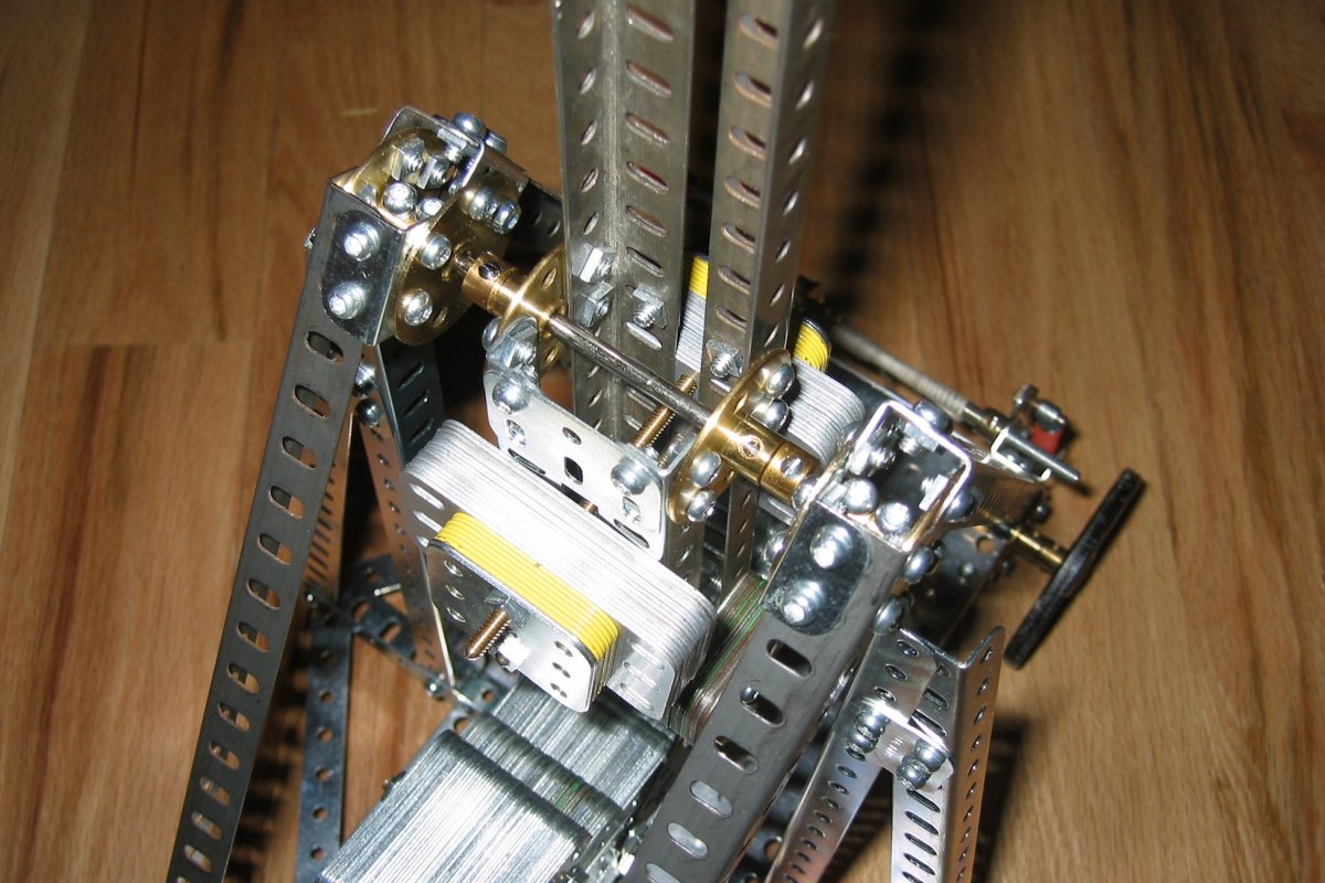
First is the cable winding drum and its drive. This subsystem includes
a cable guide similar to that in a fishing reel.
Second is a mobile counterweight system in the rear section of the
bridge which will react automatically to luffing movement of the load (and
when the load is lifted off the ground). This will make sure the bridge
maintains a continual balance over the tower.
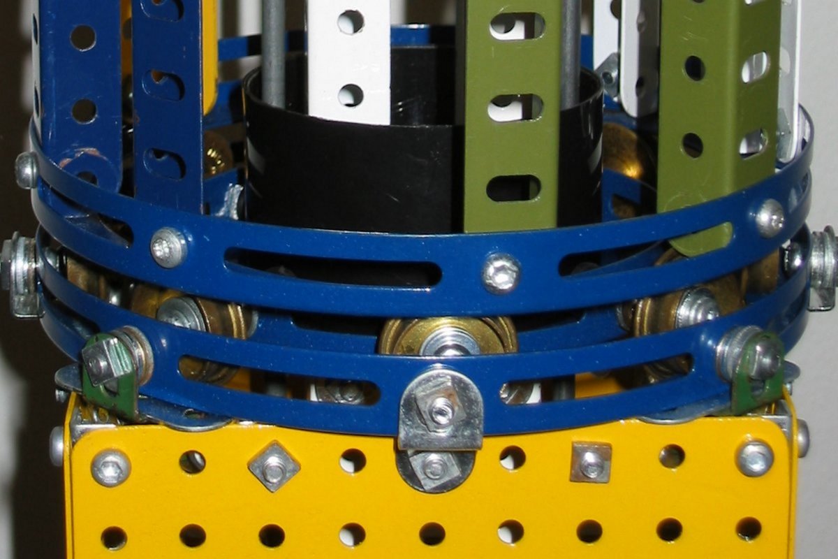
Third is a slip ring commutator which I am developing and making myself.
This will allow the bridge full rotational capabilities without tangling
any power and control wires between the tower and bridge. If you look at
image 1, you can see a black plastic cylinder at the centre of the system.
This is actually the cap from a can of spray paint. I have two of these
(the other is above the top edge of the picture). The commutator slip rings,
which will be made of a flexible plastic sheet with conductive traces on
it, will be wrapped around these cylinders. The wiper arms which
contact the traces will be replicas of parts from the Meccano Elektrikit
and will be mounted on the support collumns (blue and green angle girders).
Fourth is the trolley drive. It will be tucked in with the cable drive
on top of the rear section of the bridge and is only partially developed
at this time.
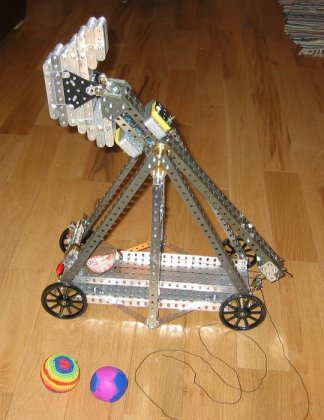
The trebuchet was a seige weapon used in mediaeval Europe till it
was rendered obsolete by the introduction of reliable cannons. These weight-powered
slings were used by armies to throw boulders at castle walls in an effort
to smash their way in. Like their cousin the catapult, they were also used
to hurl diseased bodies, the heads of captured enemies and other horrors
into the castle itself. Nasty stuff.
My model will not be used for anything nearly as neffarious as that.
This was an extremely enjoyable model to build and is even more enjoyable to demonstrate for people. This machine has 10 pounds (4.5 kg) in counter weights and can throw a hackie sack over 40 feet (12 m) with incredible accuracy. Three or four shots in a row at the maximum range will almost always land within a couple of feet (0.6m) of each other, usually within one foot (0.3m).
For a small video (795 kB AVI file) of an early version of the trebuchet, click here. Notice that the earlier version has a much smaller counter weight and a thicker throwing arm. As I tried to achieve longer ranges, these parts were changed again and again.
Detail Shots (click on the thumbnails for larger JPEG images)
 |
 |
 |
 |
 |
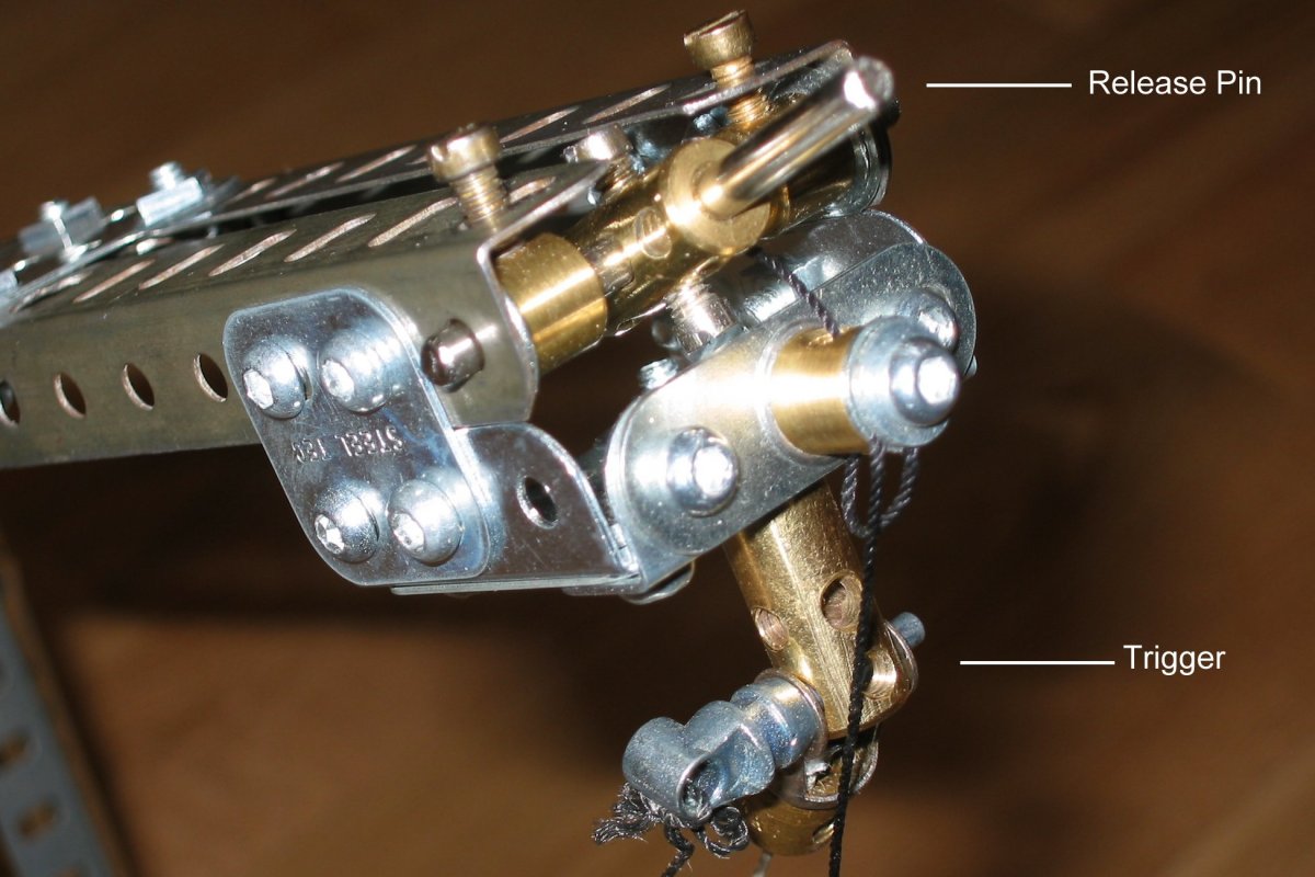
| 1. Counter Weights | 2. Release Pin and Trigger | 3. Main Bearing | 4. Winch | 5. Other Details |
I build very few models from the plans supplied with Meccano sets
these days, but I had some really nice red 1" pulleys from the 1937-41
era so I thought I'd build a couple of cars with them. The top car is
model 3.4 from the 23/69 model book and is not built with authentic colours
The green and red are from a different era but these parts were relatively
scratch-free. This model is also built with brass nuts and bolts. I don't
have many of these so I thought a small model would be their best use.
The bottom car is model 3.7 from the 162163 model book and other than the
wheels, it is built with authentic colours of the period ('70's). Other
than the colour of the wheels, there is one other deviation from the model
plan. Instead of using two overlapping 2 1/2 x 2 1/2 flexible plates
for the body just in front of the driver, I used a single 2 1/2 x 3 1/2
plate. Because of the lack of bolt holes where I needed them, this prevented
me from installing the windshield. Oh, well. The driver can wear goggles.
The models are photographed on a gloss black coffee table. Click
here for a larger picture.