| This two meter wing looks deceptively simple but it has some advanced features. The airfoil is different at the wing tip and the planform incorporates some twist. This wing is unusual in that it is very aggressive on the performance yet also has exceptional low speed handling. It is really 3 panel per side design. I sand the last couple inches of the wing round after cutting the foam. I simulated it as a four panel wing including some of the tip rounding. |
| The airfoil is a SA7035 at the root and both panel breaks. The airfoil is a SA7038 at the wing tip. The wing tip panel is mildly twisted so that it has 0.7 degrees of washout at the tip. This washout is most easily incorporated by building it into the foam cutting template for the wing tip. The twist does two things. First, the entire wing can go through the zero lift angle of attack at the same time. If the twist was not present, the wing tips would be working against the rest of the wing at high speed. |
The SA7038 has a little more camber than the SA7035. The washout in this design is the perfect amount to cancel out the little extra lift created by the SA7038. I.e. The washout angle is the same as the difference between the zero angles of attack of the two different airfoils. By allowing the entire wing to pass through zero lift coefficient at the same time, it maximizes the plane's high speed potential. The second thing the washout does is give some margin against tip stall. Tip stall margin enhances the plane's handling characteristics.
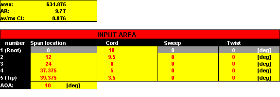
In the 4 panel LiftRoll spread sheet you can model the planform as shown below. Note that I simulated the twist as zero everywhere. The twist needed for the input to the spreadsheet is RELATIVE TO THE ZERO LIFT ANGLE OF ATTACK. Thus the sum of the zero lift angle of attack and my twist is zero. If I had NOT put the washout in the wing, the change in airfoils would have given effective wash in. To see the effect of the effective wash-in, run the spreadsheet with 0.61degrees twist at the third break and 0.7 degrees at the wing tip. Positive values give wash-in.
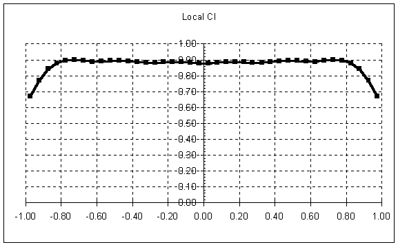
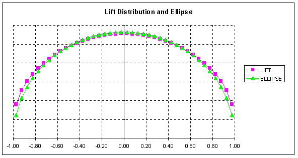
The zero lift angle of attack only matters when you are using multiple airfoils on the wing. If you look at the cl distribution, it is nearly constant over the inner 80% of the wingspan. Aggressive performance planforms will use a constant cl for most of the wing. The "naive" designer would use an elliptical planform and get a constant cl over the entire wing. The latter would lead to tip stalls in turning flight. Some F3B designs do push the limit more than I did. I have seen those same F3B planes tip stall. Trainer or sport planes are better off with the cl tapering parabolically away from the root of the wing. A constant chord wing is the classic example of this.
I created these foam templates:
| station | chord | twist | airfoil | 1 | 10" | 0 | SA7035 | 2 | 9.5" | 0 | SA7035 | 3 | 8.5" | 0 | SA7035 | 4 | 4.5 | -0.7 | SA7038 |
For cutting foam, I cut these three panel blanks:
| 12" long with a 10" chord tapering to 9.5" |
| 12 long with a 9.5" chord tapering to 8.5" |
| 15.4 long with a 8.5" chord tapering to 4.5" |
Actually, I normally add another half inch to the trailing edge of the foam blanks for more consistently straight vacuum bagged trailing edges. They are trimmed to the designed size after bagging.
There are three of these two-meters in my area that have been flying for two years. A fourth has been flying for one year and a couple more are under construction. All the pilots are very happy with them. The latest ones have used fuselages from Mark Kummerow (his Searcher fuselage). Ours usually weigh about 38 ounces with 6 servos and winch-proof wings. We have yet to see a tip stall in flight. The planes can fly somewhat nose high without stalling. When forced to stall, they lower the nose, drop a little and start flying again. Landings with 90 degree flap and 30 degree up aileron are very slow and controllable. The high speed performance is also excellent. We did some 2 man F3J pulley launches with mine. A review of the video tape showed that it spent 4 seconds on the monofilament line and then flew straight up for another 5 seconds.
The same design principles can be applied to any glider wing design.
| 1. Choose panel breaks that are convenient. for example I often use multiples of 12" for foam utilization. (Spyder foam is expensive) |
| 2. Adjust the chord distribution to strive for a constant cl over the inner 80% of the wing. Use less than 80% for conservative designs. |
| 3 Reduce the cl at the wing tip 20-30% by using a finite tip chord. |
| 4. Use a higher camber airfoil at the tip with some washout. Make sure that the tip airfoil is one that tolerates low reynolds numbers well. |
| 5. The washout should be set so that the whole wing goes through its zero lift angle of attack at the same time. |
Mike Garton


