Pump head or total dynamic head is the most misunderstood topic among pond owners. Most pond owners think their pump head is between 5 and 7 feet. They are shocked when they find out that it is actually between 20 and 40 feet. Matching a pump to the pump head is vital, but seldom done.
If you buy a pump that
is way too small it may only move a trickle of water, or possibly none
at all. One that is a bit larger can still be too small to give good
aeration, filtration and surface skimming. Overloading a pump that is
too small can result in a shorter pump life, and more repairs. Often
people who buy too small a pump will buy 1 or more of the same pump, so
they wind up running several pumps with higher operating costs than 1
properly sized pump.
On the other hand,
choosing a pump that is too large will not only waste a lot of money to
run it, but can actually result in damage to the plumbing and equipment.
In order to pick out the correct pump there are 5 steps you need to go through:
- Determine the volume of your pond;
- Determine the flow you want based on the pond’s volume;
- Determine the correct pipe size to move the flow you want;
- Determine the water pressure needed to move the desired flow rate through your system;
- Determine the proper pump that will give you the desired flow rate at the required pressure.
I. Determining the volume of your pond
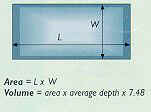
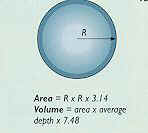
The first thing you need to do is determine the volume of you pond. If you have not done that yet it is the length (ft) x width (ft) x depth (ft) x 7.48 gallons / cubic foot = U.S. Gallons.


If your pond has a very irregular shape you may want to back-calculate its volume by measuring changes in the salinity when you add salt. There are some very good salinity test kits that are extremely accurate.
The procedure is to:
-
First measure the salinity of your pond.
-
Then add an amount of salt (Morton's Purex) that you think will raise the salinity by 0.1%. For instance, 1,000 gallons weighs 8,330 pounds, and 0.1% salt would be 8.3 pounds (1 gallon of water weighs 8.33 lbs). Make sure you do not add any new water until this test is over .
-
Measure the salinity level again after allowing 24 hours of water circulation to even out the salt concentration.
-
Subtract the original lower number from the newer higher salinity number.
-
Take the increased % salinity and use the following equation:
-
Divide the number of pounds of pure salt you added by the % salinity change times 8.33 to get the gallons of your pond.
-
For example, if you added 66 pounds of salt to get a 0.1% salinity change:
66 / (.001 x 8.33) = 7,923 gallons
-
II. Determining the flow you want
If you have a pond that
is under a few thousand gallons you may want to turn it over 2 to 3
times per hours. This is similar to large marine aquarium owners who
have learned to turn over their aquariums' water a minimum of 3 times
per hour. If it is a larger pond you may want to turn it over only once
every 2 hours.
Peter Waddington, in
his book “Koi Kichi”, says the real volume of water a fish lives in
is determined by multiplying the pump's flow per hour times 24 hours per
day. For instance, 3,333 gallons/hour yields a "real volume"
of 80,000 gallons that the Koi actually live in, regardless of the
actual size of the pond. This says that the water pump’s output is
more important than the size of the pond. So people with smaller ponds
will want to turn them over more often than those with larger ponds.
So let’s say you have a 5,000-gallon pond, and you want to turn it over every 1-½ hours. We simply divide the size of your pond by the number of hours you want for a complete turnover to get your flow rate. So for our example the flow needs to be 5,000 / 1.5 = 3,333 gallons per hour (GPH) or 3,333 / 60 = 55.5 gallons per minute (GPM).
The flow rate is very important and determines the size of you piping and pump.
III. Determining the correct pipe size for your pond
The Plastic Pipe and
Fittings Association (PPFA) says PVC pipe should be designed for a
maximum flow-rate velocity of 5 to 8 feet per second (fps) through the
pipe. They say 8 fps is ok for pipe sizes less than 1” in diameter,
but it should be less than 5 fps for pipe sizes of 1 ¼ “ or larger.
Higher velocities can actually cause pipe failure and rupture, as well
as astronomically large resistance to water flow, which necessitates
higher horsepower requirements, and higher operating costs.
How do you determine
the velocity of the flow rate in feet per second? The equation is:
Velocity
in fps = .4085 x GPM / d2
Where GPM = gallons per minute, and
d = inside diameter of the pipe in inches.
The following table
shows the results of these fps calculations for various pipe diameters
(d) and flow rates in GPH and GPM:
Table One
|
|
GPH |
600 |
1,800 |
3,000 |
3,600 |
4,800 |
6,000 |
9,000 |
12,000 |
|
|
GPM |
10 |
30 |
50 |
60 |
80 |
100 |
150 |
200 |
|
d
nom.” |
d
act.“ |
|
Velocity |
through |
pipe
in |
feet
per |
second |
|
|
|
½
“ |
0.608 |
11.05 |
33.15 |
55.25 |
66.30 |
88.40 |
110.51 |
165.76 |
221.01 |
|
¾
“ |
0.810 |
6.23 |
18.68 |
31.13 |
37.36 |
49.81 |
62.26 |
93.39 |
124.52 |
|
1.00 |
1.033 |
3.83 |
11.48 |
19.14 |
22.97 |
30.63 |
38.28 |
57.42 |
76.56 |
|
1.25 |
1.364 |
2.20 |
6.59 |
10.98 |
13.17 |
17.57 |
21.96 |
32.93 |
43.91 |
|
1.50 |
1.592 |
1.61 |
4.84 |
8.06 |
9.67 |
12.89 |
16.12 |
24.18 |
32.24 |
|
2.00 |
2.049 |
0.97 |
2.92 |
4.86 |
5.84 |
7.78 |
9.73 |
14.59 |
19.46 |
|
2.50 |
2.445 |
0.68 |
2.05 |
3.42 |
4.10 |
5.47 |
6.83 |
10.25 |
13.67 |
|
3.00 |
3.042 |
0.44 |
1.32 |
2.21 |
2.65 |
3.53 |
4.41 |
6.62 |
8.83 |
|
4.00 |
3.998 |
0.26 |
0.77 |
1.28 |
1.53 |
2.04 |
2.56 |
3.83 |
5.11 |
|
5.00 |
5.017 |
0.16 |
0.49 |
0.81 |
0.97 |
1.30 |
1.62 |
2.43 |
3.25 |
|
6.00 |
6.031 |
0.11 |
0.34 |
0.56 |
0.67 |
0.90 |
1.12 |
1.68 |
2.25 |
So we need to pick a velocity that is less than 5 fps from the above table. So looking at the above table for our example, we want to look down the 3,600 GPH column (since we want a flow of 3,333) until we find an fps that is less than 5. When we do that we see 4.10 fps corresponds to a 2-½ “ pipe.
One 2” pipe would be
pushing the envelope, but we could use 2-2” pipes; like one 2” pipe
from the bottom drain, and another 2” pipe from the skimmer. Both
pipes could terminate in the ends of a Tee fitting, with valves for
each, with the center branch feeding the pump. By the way, 2-2” pipes
have about the same area as 1-3” pipe.
IV. Determining the water pressure needed from the Total Dynamic Head (TDH), or the sum of all the sources of pump head Ph, for your design
Head is best defined as
“resistance to flow”. A higher head means you need more pressure to
overcome it. The term “head” is further modified by whether the
resistance is encountered on the suction side of the pump (suction head
(HS) from the pond to the pump) or the discharge side
(discharge head (HD) from the pump to the pond); whether it
is caused by the standing height of the water (static head hsh
= height of the waterfall or fountain above the water’s surface) or by
the movement of water through the system (dynamic head = hd);
whether the resistance is caused by simple friction due to fittings and
pipe sizing (friction head = hf ) or by the equipment
resistance (he).
TDH = HS
+ HD = (hsh + hd + hf + he)S
+ (hsh + hd + hf + he)D
In order to determine
the total dynamic head (TDH) we need to consider all of these sources:
- When water flows through pipe there is a pipe friction or resistance at the inside surface of the pipe that needs to be overcome. That friction is a function of the diameter and length of the pipe.
- When water flows through fittings like elbows, Tee’s, valves, check valves, etc. there is turbulence that also causes resistance to water flow. This resistance is a function of the total number of each type of fitting, and is expressed in feet, as an equivalent length of pipe, not as pump head.
- When water flows through a leaf-basket / strainer, skimmer, drain, etc., there is more resistance to flow, depending on the open area of that component, as well as how plugged up the holes are with algae, leaves, etc.
- When water flows through a filter, the resistance to the flow depends on the valve, filter media, size of the filter, the internal plumbing, the flow rate, how dirty it is, etc.
- When water flows through an Ultra Violet sterilizer the center UV tube increases the resistance of that section of pipe to water flow.
- A heater also will increase resistance to water flow as it squeezes the flow down into a smaller 1” tube, and makes a “U” turn in the heat exchanger, and adds more pipe length and fittings to the design.
- Another source of TDH or Ph is the static lift in the pond design. An example of this is the height of a fountain, statue, or waterfall above the surface of the pond water.
This TDH or Ph is the
most difficult calculation for everyone, because it is very complicated.
Here is a table of the resistance in feet of pump head for every 10-foot
length of pipe as a function of water flow:
Table Two
|
|
GPH |
600 |
1,800 |
3,000 |
3,600 |
4,800 |
6,000 |
9,000 |
12,000 |
|
|
GPM |
10 |
30 |
50 |
60 |
80 |
100 |
150 |
200 |
|
d
nom” |
d
act” |
|
Pump |
head
in |
feet
per |
10
ft of |
pipe |
|
|
|
½
“ |
0.608 |
7.80 |
59.66 |
153.65 |
215.37 |
366.92 |
554.69 |
1175.35 |
2002.42 |
|
¾
“ |
0.810 |
1.93 |
14.77 |
38.05 |
53.34 |
90.87 |
137.37 |
291.08 |
495.91 |
|
1.00 |
1.033 |
0.59 |
4.53 |
11.66 |
16.34 |
27.83 |
42.08 |
89.15 |
151.89 |
|
1.25 |
1.364 |
0.15 |
1.17 |
3.01 |
4.22 |
7.20 |
10.88 |
23.06 |
39.28 |
|
1.50 |
1.592 |
0.07 |
0.55 |
1.42 |
1.99 |
3.39 |
5.13 |
10.87 |
18.52 |
|
2.00 |
2.049 |
0.02 |
0.16 |
0.42 |
0.58 |
0.99 |
1.50 |
3.18 |
5.42 |
|
2.50 |
2.445 |
0.01 |
0.07 |
0.18 |
0.25 |
0.42 |
0.64 |
1.35 |
2.30 |
|
3.00 |
3.042 |
0.00 |
0.02 |
0.06 |
0.09 |
0.15 |
0.22 |
0.47 |
0.79 |
|
4.00 |
3.998 |
0.00 |
0.01 |
0.02 |
0.02 |
0.04 |
0.06 |
0.12 |
0.21 |
|
5.00 |
5.017 |
0.00 |
0.00 |
0.01 |
0.01 |
0.01 |
0.02 |
0.04 |
0.07 |
|
6.00 |
6.031 |
0.00 |
0.00 |
0.00 |
0.00 |
0.01 |
0.01 |
0.02 |
0.03 |
Where do these values come from? The PPFA says to use the Hazen-Williams Equation.
The equation is:
Ph =
104.4 / C1.852 x (GPM)1.852 / d4.8655
where Ph is the pump
head in feet per 10 feet of pipe, GPM is gallons per minute, d is the
inside diameter of the pipe in inches, C is a pipe smoothness
coefficient that is 150 for new PVC; 140 for smooth walled copper,
brass, etc.; 100 for ordinary iron pipe; and 80 for old iron pipe.
Lasco’s PVC fittings
website also uses this equation to show the friction losses. However,
they convert their results to Pounds per square inch (PSI) per 100 feet
of pipe length.
So according to the
above table, if we have 30 feet of pipe, and a flow of 3,333 GPH, the
pump head due to the pipe alone, without any fittings, would be 4.22 * 3
= 12.66 feet of pump head for 1 ¼ “ pipe; 1.99 * 3 = 6 feet
for 1 ½ “ pipe; 0.58 * 3 = 1.7 feet for 2” pipe, etc.
The next consideration is the number and type of
fittings we plan to use. Following is a table of the resistance per
fitting, expressed in length of equivalent pipe in feet, not in feet of
pump head. This is a very important distinction and is a source of much
confusion.
Table Three
|
Pipe
d " |
90º
elbow |
45º
elbow |
Tee-run |
Tee-branch |
Check
valve |
Gate
valve |
|
0.50 |
1.5 |
0.8 |
1 |
4 |
5.2 |
0.4 |
|
0.75 |
2 |
1 |
1.4 |
5 |
6.5 |
0.55 |
|
1.00 |
2.3 |
1.4 |
1.7 |
6 |
8.7 |
0.7 |
|
1.25 |
3 |
1.8 |
2.3 |
7 |
10 |
0.9 |
|
1.50 |
4 |
2 |
2.7 |
8 |
13.4 |
1.1 |
|
2.00 |
6 |
2.5 |
4.3 |
12 |
17.2 |
1.4 |
|
2.50 |
7 |
3 |
5.1 |
15 |
20.6 |
1.6 |
|
3.00 |
8 |
4 |
6.3 |
16 |
25.5 |
2 |
|
4.00 |
10 |
5 |
8.3 |
22 |
33.6 |
2.7 |
Assuming we are using a total length of
30 feet of 1 ½ “ pipe, with six 90º elbows, two 45º elbows, four
Tee’s, 1 check valve, and 10 gate valves. We use Table Three to
construct the following Table Four:
Table Four
|
Assuming
30’ length of 1 1/2" pipe |
#
of fittings |
ft
/ fitting |
Equivalent
pipe length |
|
Length
of pipe |
|
|
30 |
|
90º
elbows |
6 |
4 |
24 |
|
45º
elbows |
2 |
2 |
4 |
|
Tee's
- flowing through the run |
4 |
2.7 |
10.8 |
|
Tee's
- flowing through the branch |
4 |
8 |
32 |
|
Check
valve 100% open |
1 |
13.4 |
13.4 |
|
Gate
valve 100% open |
10 |
1.1 |
11 |
|
|
|
|
|
|
Total
equivalent pipe length |
|
|
125.2 |
Using these values we
get a total equivalent pipe length of 125.2 feet. Now we go to Table Two
and find the pump head for a flow rate of 3,333 GPH, for a pipe diameter
of 1 ½ “, which is 1.99 feet of pump head for every 10 feet of
equivalent pipe length. Using these numbers to calculate the total pump
head:
125.2 * 1.99 / 10 = 24.9 feet of pump head,
which is due to the friction losses through the 1 ½ “ pipe and fittings.
When we perform this same calculation for all the pipe diameters at a flow-rate of 3,333 GPH, we get the following results:
Table Five
|
Pipe
size |
Ph |
|
½
" |
2,696.4 |
|
¾
" |
667.8 |
|
1 |
204.6 |
|
1
¼ " |
52.8 |
|
1
½ " |
24.9 |
|
2 |
7.3 |
|
2
½” |
3.1 |
|
3 |
1.1 |
As you can see the pipe
diameter has a huge effect on the pump head requirement. If we choose
the correct pipe diameter, based on the 5 feet per second velocity
restriction, as is shown in Table One, we would use a 2 ½ “ pipe for
a flow of 3,333 GPH. This would give us a pump head of 3.1 as seen in
Table Five, and the guideline of “1 foot of pump head for every 10
feet of pipe” holds true for our 30 feet of pipe.
However, if we choose
any other size of pipe, then this guideline does not hold true, and can
be way off the mark. So choosing the correct pipe size for our pond is
absolutely critical. As seen in Table Five, if we used the 1 ½ “ pipe
the pump head would be over 8 feet of pump head for every 10 feet of
pipe.
Unfortunately this is
an easy mistake for a beginner to make, and becomes very difficult to
correct after the pond is constructed. There are too many ponds with the
wrong size pipe buried deep under the liner, or concrete, or the
waterfall with its many tons of rock and boulders.
The next step is to add
the pipe and fittings pump head to the other equipment pump head losses
(not equivalent pipe lengths) to get the Total Dynamic Head (TDH):
Table Six
|
|
Pump
head |
PSI |
|
Pipe
& fittings |
24.9 |
10.8 |
|
Bottom
drain |
2.0 |
0.9 |
|
Skimmers |
2.0 |
0.9 |
|
Leaf-baskets |
2.0 |
0.9 |
|
80
watt UV |
1.9 |
0.8 |
|
Filter |
14.3 |
6.2 |
|
Heater |
5.0 |
2.2 |
|
Static
lift of 6 feet |
6.0 |
2.6 |
|
|
|
|
|
TDH |
58.1’ |
25.2 |
All these calculations have been based on ideal “new” pipe, fittings, and equipment. Older systems may have “algae, hard mineral scale, or muck build-up" on the piping walls, filters, strainers, valves, elbows, heat exchangers, etc., making the published numbers way too low; and that is assuming there are no rocks, gravel, or tree roots in the pipe. If any of these things are present, then the smoothness coefficient is no longer valid, and neither is the inside diameter of the pipe. In other words, the TDH pump head can in reality be much higher than calculated for new pipe.
Another way of determining the TDH is to measure it, if your existing pump is working. You can install a flow meter on each of the suction lines to help you balance the system, plus a vacuum gauge on the suction side of the pump, and a pressure gauge and another flow meter on the discharge side of the pump.
Every inch of mercury on the vacuum gauge is multiplied by 1.13 feet of head to get the suction head. Every PSI on the pressure gauge is multiplied by 2.31 feet of head to get the discharge head. Then you add those two head numbers together to get the Total Dynamic Head (TDH), at your existing flow rate.
One thing that is important to remember is that the TDH changes dramatically with the flow rate. You system's head can be one value at one flow rate, and dramatically different at another one.
V. Determining the best pump that will give you the proper flow and pressure
Now we know the flow rate we want is 3,333 GPH or 55.5 GPM, and the Total Dynamic Head (TDH) for our pond design is 58.1 feet of pump head.
Our next step is to check out the various performance curves for available pumps. Graph One is a typical performance curve. We find 55.5 GPM on the X or bottom axis, and draw a line up. Then we find 58.1 feet of pump head on the Y or side axis, and draw a line to the right. Where they meet is the pump that we want.
In this case we want a pump that is a little less than a 1 horsepower pump. Our next step is to find the most efficient pump for our conditions. The most efficient pump will be the one with the highest Creech Pump Index = (GPM x TDH / watts), and if they have the same CPI, then the lowest amps.
If we can find a variable speed pump, like the
Money Saver Pump®, we can dial the horsepower and amps down to exactly
where we need it to be, and save money. This is especially true when our
GPM and TDH point falls well below the horsepower we need. We are not
using a pump that is too large because now we can dial it down to the
proper size. It is like having a pump with a gas pedal, which does not
need to be pushed to the floor all of the time. When we let up on the
gas pedal, we save money.
One thing to avoid is picking a pump with no “head” room. We want to make sure that we are not too close to the maximum pump head, in case we have not allowed for “dirty” pipes, fittings, etc., which eventually could result in no flow at all. The gas pedal allows for real world changes, and system additions and expansions.
Graph One
