Networking reminders
1.
Generals :
TCP/IP is the most used protocol.
It is based upon the OSI (Open System Interconnection) model defined by ISO (International System Organization).
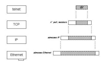
This model consists in 7 layers organized in piles and successive encapsulations.
Layer 7,6,5 = application (GUI, code, tools)
Layer 4 = datagrams (TCP, UDP…)
Layer 3 = IP, ARP, ICMP, RARP…
Layer 2 = Ethernet protocol, spanning tree, SNAP, PPP, IEEE 802.3…
Layer 1 = physical (chip, pcb, support…)
There are 4 kinds of network:
LAN (Local Area Network)
MAN (Metropolitan Area Network)
WAN (Wide Area Network)
Enterprise (combination of 3 above)
Networking topologies are defined within 3 types:
Star (each node is connected to a central one)
Ring (each node is connected to a neighbor which is connected to its neighbor which is connected to its neighbor and so on, the last one being connected to the first)
Bus (each node is connected to a bus)
Wiring:
10 Base5 or thick Ethernet (shielded coaxial 50 Ohms max length = 500 m and 10 Mb/s)
10 Base2 or thin Ethernet (shielded coaxial 50 Ohms max length = 185 m and 10 Mb/s)
10/100 BaseT or Universal cable (shielded Twisted pairs max length = 100 m and 10/100 Mb/s Manchester signal)
2. Network access method
2.1. Token ring
The Token Ring network was originally developed by IBM in the 1970s.
A token is given to a station asking to access the network.
The token is given back at the end of the session.
2.2.
CSMA/CD or Ethernet:
Carrier Sense Multiple Access / Collision Detection.
Each node is ”listening” the network.
If it “sees” a packet for him (its address is in the packet) it takes it and treats it.
If the station asks for a data transfer, it embeds the signals on the line except if the line is busy.
This cycle continues in a random way until the line is free.
This system is very dependant of the line physical characteristics. Indeed, a packet may become detectable while the station is about to ask again to access the network. Then a collision occurs (the data is considered invalid).
The involved stations send a signal to report the event and start again later in a random way.
The packets maximum size is 12144 bits and the minimum is 512 bits.
The upper OSI layers are used to put in the right order the packets arrived in a wrong one due to a different routing path.
This rustic principle is very efficient but brings the problem of segmentation.
In order to reduce the number of collisions (prevent from congestion) within a node and therefore increase the bandwidth, it’s better to cut the network in different parts.
Subnetworks are there for that purpose. They prevent the network from congestion by reducing the number of stations on a node.
Packet format:
![]() The first bits are packet delimiters
and preamble.
The first bits are packet delimiters
and preamble.
![]() The following ones represent the EMAC
of the recipient and made of 6 bytes (00 c0 a4 23 d4 02)
The following ones represent the EMAC
of the recipient and made of 6 bytes (00 c0 a4 23 d4 02)
The first 3 represents the manufacturer, the 3 others are for the equipment (manufacturer can have 2 power 24 = 16 777 216 stations).
![]() The 0x ff ff ff ff ff ff is reserved for
the broadcast (each equipment on the node got the info)
The 0x ff ff ff ff ff ff is reserved for
the broadcast (each equipment on the node got the info)
![]() The third block represents the EMAC of
the transmitter.
The third block represents the EMAC of
the transmitter.
![]() The following block is for the packet
type, its length vary depending on the kind of frame used (Ethernet II or
802.3).
The following block is for the packet
type, its length vary depending on the kind of frame used (Ethernet II or
802.3).
![]() TCP/IP uses only Ethernet packets but
Netware can do both.
TCP/IP uses only Ethernet packets but
Netware can do both.
![]() The larger block is used for data.
The larger block is used for data.
![]() The last bits are used for CRC
(Checksum)
The last bits are used for CRC
(Checksum)
The number of equipments is very high (2 power 64), so to manage the network, logical addresses are used.
Those addresses are the intelligent way of interconnecting a great number of equipments.
This is called routing.
2.3. TCP/IP
2.3.1. Generals:
It comes from the linux world and was made before ISO, therefore lightly different.
The IP (Internet Protocol) layer is used to manage logical addressing and to transfer the packets.
It uses some mechanisms like packet repetition and variable window reception.
2.3.2. IP addresses :
Class A first bit equal zero addresses from 1.0.0.0 to 127.0.0.0 several network per country WAN
Class B first bit equal 1 and the second equal zero 128.0.0.0 to 191.0.0.0 several thousands network MAN
Class C first bit equal 1 and the second equal 1 and the third equal 0 128.0.0.0 to 191.0.0.0 several thousands network LAN
2.3.3. Mechanisms :
When a packet is sent, the recipient node “sees” that the info is for him by reading the EMAC.
This prevent from using too much the upper layers.
Tables are managed to put together the right EMAC with the right IP addresses using ARP (address routing Protocol) allowing a correct routing for data.
2.3.4. Domains:
To prevent from the very hard job to remember the addresses 1.111.123.234, 122.0.0.100 etc.., the domain name system was created .
The DNS (Domain Name Service) is the first server contacted when initiating a connection.
Each network got a particular name and is unique.
Each node got a particular name and is unique.
This service is managed by the NIC.
2.4. UDP :
UDP (User Datagram Protocol) is a layer at the same level as TCP.
It is similar to TCP but without data control.
Above it and using it is SNMP (Simple Network Management Protocol).
2.5. EMAC:
Every station or equipment has got an EMAC address (Ethernet Media Access Control).
It is unique and is made of 12 hex coded numbers (0x00809f3b1234).
You cannot have 2 similar EMAC, if that happens anyways and if both equipments try to access the same network at the same time,
errors occur and it may block the network.
Every manufacturer can buy EMACs by slices like 0xYY YY YY xx xx xx (the Ys represent the slice and the Xs the equipment).
2.6. Novell network :
Netware is the network that was created by NOVELL.
It handles the IPX and Netx protocols and applications proper to its environment.
The network number is made of 8 hex characters and is called external net.
The server number is made of 8 hex characters and is called internal net.
Every server connected to a same segment must have the same net name (external net).
Addressing with Novell:
For servers = internal net + Ethernet
For stations = external net + Ethernet
Example of names: SHC01, SHCCIC…
3.

Routers:
A router also called gateway has at least 2 equipments with a physical and logical address for each one.
It can be connected to the public network using a modem and therefore to another one using the same protocol (Remote router).
It can also be used as a bridge between 2 sub networks.
For example 100 stations gathered into a department are communicating very often one to another (Email,ftp,Voip…) and from “time to time” need to connect to an other department gathering 50 stations .
Using those bridges they can exchange TCP/IP info and Ipx/Netx as well.
There purpose is to transfer data from a node to another, this is called routing.
In order to minimize the transfer time, a lot of specialized protocols are used to find the best and shortest path to reach the recipient.
They use algorithms based on mathematics to solve this fundamental problem of internetworking.
In this diagram we
can see that packets coming from A node toward B node can take different paths
to reach their targets.
Those paths have of course different ‘length” (speaking about time), depending on the wiring, the speed of each router, the bandwidth, the way the router is administrated …
Considering the complexity of the internetworking
today, the number of protocols used, the different kinds of info to transfer
(Emails, Video, Voice, Banking…) a great challenge exists to increase the
bandwidth and the quality of service as well.
It is possible to get into it by keeping trace of the routing failures, analyzing them and understand what happened when these failures occurred.