Spanning Tree Protocol IEEE 802.1Q summary
Generals
STP is a layer-2 protocol that uses MAC
addresses to send data from a station to another.
It provides path redundancy and in the meantime prevents undesirable loops in a network.
Only one active path can exist between 2 stations to make the network function properly.
When a network is wired, a certain number of redundant connections are made in order to prevent interfaces and-or switches failures.
Those connections give a stronger safety for a better network but increase the possibility to have loops and therefore decrease the bandwidth of this network.
If those loops happen too often a big congestion may occur.
STP defines a tree that spans all switches in an extended network.
It forces certain redundant paths into a blocked state (standby).
In case of unreachable segment or costs change, the STP algorithm reconfigure the spanning tree and keep the link in function by activating a previous standby path.
Election of the root switch
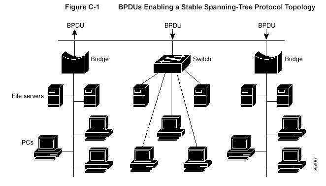
All switches involved in the STP gather info on other switches by exchanging data messages.
These messages are called BPDUs (Bridge Protocol Data Units).
They are used to:
- Elect a unique root switch for the stable network topology.
- Elect a designated switch for every segment.
- Remove the loops by placing redundant links into a backup state.
The root switch is the logical center of the spanning-tree topology network.
All paths that are not needed to reach the root switch from anywhere in the network are placed in spanning-tree protocol backup mode.
Variables used in the STP
Hello Time:
Determines how often the switch broadcast its Hello message to the others.
Maximum Age Timer:
Measures the age of a received info.
Ensures that this info is discarded when its age limit exceeds the value of the maximum age parameter recorded by the switch.
The timeout value is set to the maximum value found in the network.
Forward Delay Timer:
Monitors the time spent by a port in the learning and listening states.
The timeout value is the forward delay parameter of the switches.
BDPU:
Contains info about the transmitting switch and its ports.
It means switch and ports MAC addresses, switch priority, and port costs.
It is used to elect the root switch, the root port and the designated port for each switched segment.
The switch sends configuration BDPUs to communicate and compute the spanning-tree topology.
All switches connected to the LAN receive the BTPU.
BTPUs are note directly forwarded but it is used to calculate a BTPU and if the topology changes, instigate a BTPU transmission.
BTPU exchange results in:
- One switch is elected as root.
- The shortest distance to the root switch is calculated for each switch.
- A designated switch is selected. This is the closest to the root switch.
- A port for each switch is selected. The port providing the best path.
- Ports included in the STP are selected.
STP configuration
With default settings, the root switch is the one with the smallest MAC address.
But due to the traffic, it may not be the ideal one.
This can be changed by increasing the priority of the best one, and then, forcing a recalculation of a new stable topology.
STP port states
It uses 5 states to operate:
- Blocking:
After a port initializes, it begins in the Blocking state so that no bridging loops can form.
In the Blocking state, a port cannot receive or transmit data and cannot add MAC addresses to its address table.
A port is only allowed to receive BPDUs.
In addition, ports that are put into standby mode to remove a bridging loop enter the Blocking state.
- Listening:
The port will be moved from Blocking to Listening if the switch thinks that the port can be selected as a Root Port or Designated Port.
In other words, the port is on its way to begin forwarding traffic.
In the Listening state, the port still cannot send or receive data frames.
However, the port is allowed to receive and send BPDUs so that it can actively participate in the Spanning-Tree topology process.
Here the port is finally allowed to become a Root Port or Designated Port because the switch can advertise the port by sending BPDUs to other switches.
Should the port lose its Root Port or Designated Port status, it is returned to the Blocking state.
- Learning:
After a period of time called the Forward Delay in the Listening state, the port is allowed to move into the Learning state.
The port still sends and receives BPDUs as before.
In addition, the switch can now learn new MAC addresses to add into its address table. This gives the port an extra period of silent participation and allows the switch to assemble at least some address table information.
- Forwarding:
After another Forward Delay period of time in the Learning state, the port is allowed to move into the Forwarding state.
The port can now send and receive data frames, collect MAC addresses into its address table, and send and receive BPDUs.
The port is now a fully functioning switch port within the Spanning-Tree topology.
- Disabled:
In this state a port receives BTPUs but only responds to management messages.
Changes from a state to another:
A port moves through the 5 states as follows:
- From initializing to blocking.
- From blocking to listening or disabled.
- From listening to learning or disabled.
- From learning to forwarding or disabled.
- From forwarding to disabled.

You can modify each port state by using management
software.
When STP is enabled, every switch in the
network goes through the blocking state and the transitory states of listening
and learning at power up.
If properly configured, the ports then stabilize to the forwarding or blocking state.
Costs
IEEE Cost values allocated to Ethernet Interface.
|
Speed |
Cost or Value |
|
4 Mbps |
250 |
|
10 Mbps |
100 |
|
16 Mbps |
62 |
|
45 Mbps |
39 |
|
100 Mbps |
19 |
|
155 Mbps |
14 |
|
622 Mbps |
6 |
|
1 Gbps |
4 |
|
10 Gbps |
2 |
Spanning Tree Protocol allows a network to have redundant interfaces, but only one interface at a time will be active, so with spanning tree, there is no load sharing.
All interfaces either go to forwarding or blocking states.
A reference point is required. In an STP enabled configuration, this is called the root bridge and is elected automatically by the network switches.
Bridges listen for 'hello timer BPDUs'. When they don't hear tem anymore, they go into a max-age state (20 seconds) and then start looking for low cost BPDUs on other interfaces.