
My reference image, a skull X-ray from a music video. This image is useful because of the high contrast and large shapes
The text video player displays moving pictures in a Windows console window, or "DOS box," by approximating the shapes in the picture with ASCII characters. Because it is a drop-in replacement for the default Windows video renderer, it will play any video data for which DirectShow codecs are available, including MPEG-1, AVI, and Windows Media.
This project started about four years ago when, in a random moment of madness, I wondered whether a graphics library could be made to display ASCII art instead of pixels. I guessed that it was impossible, because the shape-matching logic would be too slow. Two years later I heard about Jan Hubicka's Ascii Art library, which did exactly what I had thought of. It was a reminder that ideas get implemented by trying them, not by wondering whether they are possible. Simon Jansen's hand-drawn ASCII animation of "Star Wars" gave me additional inspiration. My recent layoff finally gave me time to go ahead with the project, and I turned it into an exercise to practice Windows programming (primarily COM) while having fun.
At first this idea must sound terribly pointless and wasteful, but it is similar to functionality that I have seen in shipping products. A company called Tandberg TV makes rack-mounted MPEG encoders with small monochrome LCD interface screens. These encoders can be set to display the video input on the screen, with regions of the image dithered according to their luminance (brightness). My task differs only in that I use ASCII glyphs instead of dithering patterns.
Demo instructions (Please read all of this paragraph!): To run the demo, extract the zip file into a separate folder. Open a DOS window and change to that folder. Type "player" followed by a space, followed by the filename of a video file. The player should work on any video clip in AVI, MPEG-1, or Windows Media format. If you don't have a video clip, you can download a short one below. I do not recommend playing long clips! If you interrupt the player before the clip ends, the text video player will not uninstall its components properly. If this happens, run the player again on a short clip and let it finish.
This program was written by a novice Windows programmer. There may be configurations that the program is not prepared to handle. Do not use this program on any system with unrecoverable data.
Download the demo (zip format).
Download a sample video clip (AVI format).
Download the source code (zip format).
The project has already been active for about two weeks. Here is a brief summary of where I am.
I have used the base class library included with the DirectShow development kit as a starting point for my renderer. The renderer inherits from the CBaseRenderer class and implements two abstract methods: CheckMediaType and DoRenderSample. It accepts UYVY formatted video data. UYVY is a format commonly used in television systems where each horizontal pair of pixels is represented by four values. The two Y values indicate each pixel's brightness. The U and V values indicate, respectively, the amount by which the two pixels contain more blue than green, and more red than green. The lower color resolution is acceptable because the eye is less sensitive to color variations than brightness variations.
In the first trial, I set up a very crude matching algorithm: If a character cell's average brightness is less than 128, it's a space, otherwise it's a "@". Then I agonized for several days trying to decode Y41P formatted data, which was the first format that Windows offered. I read the MSDN documentation and asked around on IRC and in various newsgroups but nobody answered. I was rescued by an article in MSDN magazine that encouraged me to switch to UYVY.
My reference image, a skull X-ray from a music video. This image
is useful because of the high contrast and large shapes
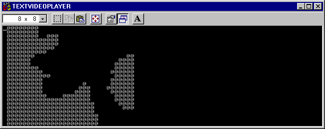
Rendering with each character cell either on or off
With this matching algorithm, high-contrast shapes are recognizable. To push up the resolution and allow varying brightness values, I chose an algorithm based on the brightness levels of the four quadrants of each cell. The character drawn in each cell is the one for which the quadrant brightness levels are closest to the brightness levels in the corresponding part of the image, as determined by a least-squares formula. By quantizing quadrant brightness into four levels, I can look up the right character in a 4x4x4x4 table. I generated a Perl script to read in a bitmap containing the font glyphs and produce the lookup table.
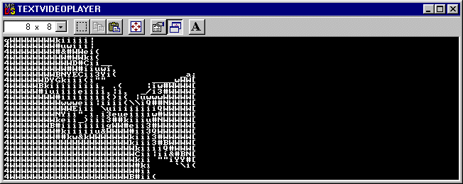
Rendering with the quadrant matching algorithm
Although this was an improvement, it was pretty clear that there was a mistake somewhere in my implementation. The jawbone, for example, should be much darker. However, I get excellent frame rates with this approach; in the video the skull's jawbone is moving, and this is clearly visible in my renderer. If I stand back from the screen I can even identify small, low-contrast moving objects.
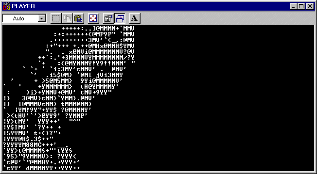
Yesterday when I tested my shape-matching algorithm, I noticed that black parts of the reference image did not appear black. They usually contained the 'i' character. According to my table, this character is used when all of the quadrant brightness levels are 1 in the range 0..3. I set a breakpoint on one such cell and found that its average brightness was approximately 0x20 (out of 0xff). My decision to round to the nearest quantized brightness level meant that the cell would be treated as if its brightness were 0x40. I replaced the round-to-nearest arithmetic with a simple round-down. This greatly improved the contrast. Then I increased the number of quantization levels to 8.

Rendering with round-down quantization to 8 levels
With a little squinting and some imagination you make out the bumps in front of and behind the vertebrae. To further demonstrate the resolution, here is another image that shows someone doing a backflip in the background. She is identifiable in the text rendering also.

The backflip image

Text rendering of the backflip image
The actual quality is a little better than these still images can show. As objects move around the screen, the viewer can estimate where their edges are. If I squint really hard I can make the image look like a detail of a two-tone newspaper image. This completes my original goal for the project, which was to render MPEG video using only two-color ASCII glyphs. The next steps are to improve the quality to that of aa-lib by using gray levels, and then to add color.
First, however, there is a stability problem I need to take care of. My player always crashes after it runs. This is probably because I haven't properly registered the renderer as a COM object. I have been learning COM as I go! I have to move the renderer class into a DLL with all the necessary plumbing, as described in the MSDN Magazine article.
After 3 days of struggling with DLL registration, entry points, and unresolved symbols, I have moved my renderer into a DLL. The player program no longer crashes after it runs. Unfortunately, I had to link in "msvcrt.lib" to complete the build. I'm worried that this could cause the program not to run without Microsoft Visual C++.
My next task is to use gray levels to improve the matching quality. For this purpose I need to define "shape" in a way that doesn't depend on a cell's overall brightness and contrast. The shape will be matched by a glyph, and then the background and foreground colors will be set to give the appropriate brightness levels. This improves on aa-lib, which does not use background colors!
One way to define the "shape" of a cell is the boundary between brighter areas and darker areas. So I need to decide on a test for a pixel to be part of the brighter area. I considered comparing to the median brightness of the cell, but this would make every cell 50% bright. Most glyphs are not as balanced. It makes more sense to apply a linear contrast-enhancing function to every pixel so that the overall range of brightnesses is the maximum possible range, 0..255. In other words Y(adjusted) = 255(Y-min)/(max - min) where min and max are the minimum and maximum brightness levels in the cell.
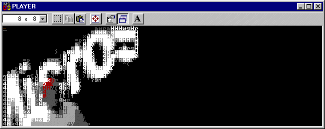
Today's image is from the infamous video of Steve Ballmer jumping around at a Microsoft employee rally. The Microsoft logo is visible in the background.
My results with the gray-level algorithm are quite pleasing. Below is a rendering of yesterday's image that says it all. View it from a distance!


I thought some more about the way I distinguish between bright and dark areas. I really need the median of all distinct brightness levels in the cell, rather than the mean cell brightness. However this value seems rather expensive to calculate.
I still have not uploaded the code due to virus concerns. This web page is supposed to be read by employers, and sending the boss a virus doesn't make a good impression! I will upload the project after I get a virus scanner and scan the executable files.
When I added the gray-level code, I reorganized the code to give it a more pipelined structure. The stages in the pipeline are as follows:
The code is much more manageable this way, but at a significant speed cost. The video becomes desynchronized with the audio, and the audio stutters after a few seconds of play. I need to move the drawing code into a separate thread, so that it accepts a new sample only when it is ready. I suspected before I started the project that a separate thread would be needed, but I have left it out until now to avoid overcomplicating the program.
I added a separate thread for drawing, and this resolved the video slowdown problem I noted in the previous entry. When the class receives a video sample, it checks whether the thread is idle. If the thread is idle, the class passes the sample to it; if not, the sample is thrown away. This communication is managed by two Windows synchronization objects: a mutex that protects access to the current sample, and an event that signals the thread that a sample has been received. In my first attempt, I passed the sample by saving a reference to the IMediaSample interface, but this caused the playback to freeze immediately. Apparently the upstream filter does not want my class to hold onto the sample. My solution was to copy the picture data out of the sample.
After I had resolved that issue, I moved ahead with the color matching. My approach was to average the colors over the dark and bright regions separately, convert these average colors to hue/saturation/intensity, and match console colors to those values according to the following rules:
Unfortunately, this approach did not work. Parts of the console window that were outside the active video region appeared white instead of black. I would like very much to replace the YUV format with RGB so that I can be more confident of the RGB->HSI conversion. However, this would not advance the practical goal of the project, which is to learn Windows APIs. Therefore I will set aside the text video renderer, knowing that I have at least outdone both my original idea and aa-lib.
I finally got to test my program on another computer. It ran just fine, although the frame rate was very low on the hardware. While I had the project open, I went ahead and converted everything to the RGB color space, and tried color matching. It took me a while to figure out why only green and magenta areas had the correct color; it turns out that the colors in the video data are in the order BGR instead of RGB. Once I got past that issue the images became more reasonable, but still ugly. Here's the usual reference image with color-matching enabled.
The only color that comes through is the pink in the man's face, but it appears as red. The blue in his shirt doesn't show up at all because it's not saturated enough. I prefer the black and white image by far.
To match the colors, I used an RGB->HSI formula from the book Video Demystified:
intensity=(R+G+B) / 3
saturation=1 - m / M where m=min(R, G, B) and M=max(R, G, B)
r = R - m; g = G - m; b = B - m.
hue=arctan(g sin 60° / (r - g cos 60°)) if b=0,
hue=120°+arctan(b sin 60° / (g - b cos 60°)) if r=0,
hue=240°+arctan(r sin 60° / (b - r cos 60°)) if g=0.
Fortunately I didn't have to calculate the entire hue formula. If, for example, blue is the smallest component and r > 2g, then the hue is closest to red. If g/2 < r < 2g, then the hue is closest to yellow. I made tests like this for each possible ordering of red, green, and blue.
I also tested the effect of making the median brightness value the threshold between dark areas and bright areas. As I expected, it produced a definite slowdown in the frame rate. I stuck with the mean-value approach instead.
I have returned to my previous employer for a while and don't have as much time to work on this portfolio. While designing a palette reduction algorithm this week, I did a lot of research on color. In the course of this research, I had a new idea for adding color to the text video player. The real breakthrough came when I looked at the color editing tool in Microsoft Paint. A screen-shot of the tool is shown below.

The tool displays colors in two color spaces: RGB and Hue/Saturation/Luminosity. By fiddling around with the values I was able to reverse-engineer the formulas:
max=max(R, G, B); min=min(R, G, B)
luminosity=240(max + min) / 510
saturation=decreasing function of min / max
hue=40(G / 255)+40((255 - R) / 255) from red to green
hue=80+40(B / 255)+40((255 - G) / 255) from green to blue
hue=160+40(R / 255)+40((255 - B) / 255) from blue to red
In the display, each of the 16 console hues corresponds roughly to a rectangular region, while intensity corresponds to the luminosity scale. Contrary to the assumption in my previous color-matching approach, the hue regions do not have the same width! I selected boundaries between the hues and wrote a new color-matching algorithm based on these boundaries. This algorithm produced impressive color matching in some parts of the picture; the magenta stage lighting in the Ballmer video was matched perfectly, as were the hints of blue in the skull image. However, the spatial resolution suffered, and skin tones came out as a mixture of magenta and yellow; a typical caucasian skin tone is R=238 G=200 B=176, which just doesn't match well to any console color. I went back to the grayscale algorithm once again.
Between the last entry and this one I went to Stanford and got a Master's degree in computer science. While waiting to start my next job, I started fiddling with this project again and couldn't stop until I had redone the whole pipeline. For starters, the idea of using mean brightnesses to choose foreground and background colors was just silly; it had no basis in image perception. The new pipeline works as follows:
I don't think I've mentioned step 5 before, but it was already there, lumped into the shape-matching. The results look like this:

Obvious improvements:
My main thought when I look at this image is, how could I have thought the last approach was good?
I haven't put the code up yet because I still get an error message at termination. Stay tuned.