Think-a-Dot Introduction
Operation
The Think-a-Dot is operated by dropping a ball into one of the three holes on the top. The ball then causes the flip-flop below that hole to change its position and also to drop the ball down to the next level. If the ball hits a blue dot it will go to the left; if it hits a pink dot, it will go to the right (viewing from the front).K'nex Build Description
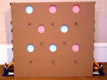 This shows the complete Think-a-Dot with the front panel in place. The panel is
actually rectangular; the odd shape is due to the camera's parallax. The photo
shows the three rows of colored dots. Below the dots we can see the grey
connectors that are used as mounting clips for the cardboard panel. These are
connected to red rods that will be shown more clearly in other photos.
This shows the complete Think-a-Dot with the front panel in place. The panel is
actually rectangular; the odd shape is due to the camera's parallax. The photo
shows the three rows of colored dots. Below the dots we can see the grey
connectors that are used as mounting clips for the cardboard panel. These are
connected to red rods that will be shown more clearly in other photos.
|

This view is from the back, with the front panel removed (there is no rear panel). The flip-flop orientation is not the same as the first view. This photo shows the structure and the mechanism that it supports. The mechanism consists of eight flip-flops. Each flip-flop has mounted on it a piece of card so that when the flip-flop is tilted to the left (viewed from the rear) blue is shown through the front panel hole. When tilted to the right, pink is shown. Notice that there are nine horizontal rows and eight vertical columns of rods. Originally, all vertical rods were blue, but I replaced the ones over the flip-flop rows with white rods to reduce the distance that the ball dropped. This was to reduce the ball's energy and force with which it hit the flip-flops. This was causing the flip-flops to sometimes bounce twice, returning to their original position after being hit by the ball. |
 This top view shows the three holes into which the ball may be dropped. Notice
the green rods that narrow the effective diameter of the holes. This is
important to reduce the tendency of the balls to fly about and result in
erratic behavior of the flip-flops. Green rods are similarly placed above each
of the flip-flops.
This top view shows the three holes into which the ball may be dropped. Notice
the green rods that narrow the effective diameter of the holes. This is
important to reduce the tendency of the balls to fly about and result in
erratic behavior of the flip-flops. Green rods are similarly placed above each
of the flip-flops.
|
 This rear 45° view shows a few additional details. Almost all of the yellow rods were
inserted to prevent the ball from escaping. You can also see grey connectors
around the blue rod on the left of the picture. These hold the diagnal yellow
rods that act to guide the ball to the middle flip-flops.
This rear 45° view shows a few additional details. Almost all of the yellow rods were
inserted to prevent the ball from escaping. You can also see grey connectors
around the blue rod on the left of the picture. These hold the diagnal yellow
rods that act to guide the ball to the middle flip-flops.
Rows 2, 4, and 6 have white connectors as the supports. There are also various white connectors used to block openings where the ball can sneak through. However, this is a bit ugly and I will replace the white connectors with rods. |