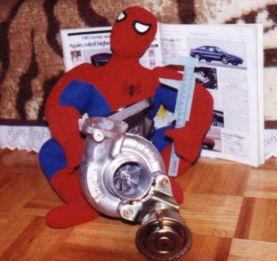
Spidey and the Mitsubishi TD-05 16G turbocharger. Behind is the 1994 Car&Driver issue containing a review of the Probe GT.
The 16G is on the smallish side compared to some of the T04/T3 hybrids people often bolt onto imports. It was designed for the
Mitsubishi 2.0L-4cyl and capable of over 350hp. In case you are curious, the compressor inlet (shown) is 2.25" in diameter, and the compressor outlet is around 1.75".
I purchased this turbo through a bulk buy organised by www.atmosphereperformance.com for less than it would have cost me to buy a refurbished T3 unit.
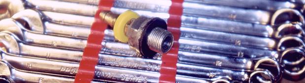
Quel artiste! An example of one of my many makeshift parts. The block oil tap used a M16*1.25mm thread, and the turbo used
a M12*1.25mm thread. Summit Racing did not have the fittings I needed, the Chrysler dealer wanted nearly $100 (remember,
there are no Mitsubishi dealerships in Canada), and nobody else carried anything even close (I have since found some sources for
fittings). In the picture above, I took a 16mm drain plug, drilled a 11/32" hole along its axis, tapped a 1/8"NPT thread, then
screwed in a 1/8"NPT barbed fitting. J.B. Weld was used to secure the threads and prevent leaks. The same process had to be done on the M12x1.25" oil feed hole on the turbocharger (see below). 
1: Oil feed (nice fitting!)
2: Coolant line (1/4"NPT plumbing fitting)
3: Compressor exhaust: Used some aluminum stock cut to size, and J.B. Welded on a short piece of pipe.
The oil for the turbo was to come from the block tap. Warning: the threaded hole is easy to strip!
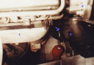
A picture of the block oil tap (arrow). An 8mm allen key can be used to remove it. Most people are unable to remove the allen bolt because it is fused in place. If
this is the case, the oil feed must be taken from the oil pressure sender which is located farther away.
1: manifold heat shield
2: distributor
3: clutch bleeder screw This is the oil pan with the drain line from the turbo attached. The pan had to be removed, a hole drilled, and a 1/4"NPT barbed
fitting J.B.Weld-ed in place. Felpro makes an oil pan gasket, but I decided to use blue silicone. It turns out that the silicone makes a fine seal, and has the added benefit of keeping the pan screws from working loose.

1: Bosch 72142 oil filter
2: A/C compressor mount
3: Oil pan What's wrong with this picture? Anybody who knows Mitsubishi 16G turbos will notice that the turbine housing has been rotated,
and the wastegate mounting changed. I later had to further rotate the compressor and turbine housings again to allow the oil drain
to point in a more downward direction. The oil drain fitting is indicated by the '2'. Because this was a weird-ass Mitsu fitting, I had
to make my own. I took a small piece of steel stock, cut it to shape, drilled a hole, and J.B. Weld-ed a 1/4"NPT fitting in. A bead of silicone was used to ensure a good seal against the turbo.
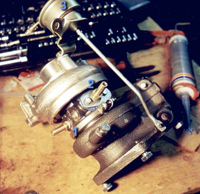
1: Coolant fitting (1/4"NPT)
2: Oil drain fitting
3: Wastegate

My less than useful helper.
Pictures of the completed system... |
