|
|
|
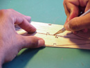
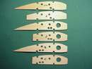
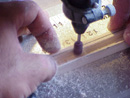
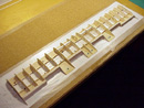
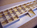
The wing of the full size OV-10 Bronco incorporated a semi-symmetrical airfoil (NACA 64A315). Instead the flat bottom Clark Y airfoil was shown on the construction plans. The outline of each rib was transferred to balsa sheets by tracing around a template with a felt tip marker. All the ribs were cut by hand (photo #1). Once all the ribs were cut and notched, they were stacked and sanded to its final shape. I used a file to make all the notches uniform (photo #2). The holes for the aileron and flap linkages were punched using a Ľ inch hole puncher. Holes were also punched for the pneumatic retract tubing and navigation lights. A larger hole was cut in forward of the front spars for the servo extension cables (photo #3).
|
|
|
|
|
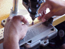
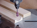
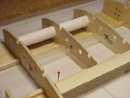
The pivot joints for the ailerons and flaps were recessed to enhance the scale appearance of the model. I used a Dremmel © tool and Typhoon Carbide burrs distributed by Micro Mark © to cut the 1/4 inch thick balsa planks. I positioned the burr at the desired cutting height with a Dremmel © drill press attachment. Photos #4 and #5 show the cutting process. I cut the edges of the groove first by sliding the wood pass the burr once on each side. The center of the plank was cut after the drill press was re-adjusted for a deeper cut. I sanded the parts to its final shape with sandpaper glued to a round dowel of the appropriate size. Photo #6 shows the final shape of the wing pivot point.
|
|
|
|
|
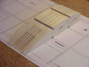
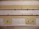
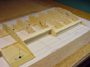
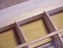
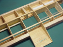
Assembly of the wing was straightforward. The 1/32 bottom sheeting was cut to size and pinned down (photo #7). The 1/4 inch square wing spars were also cut and tack glued to the bottom sheeting (photo #8). The ribs were glued to the spars and to the bottom sheeting (photo #9).
|
|
|
|
|
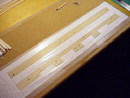
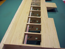
Plastic straws were added to support and protect the navigation light cables and retract airlines. A paper tube was added for the servo extension cables (photo #10). The aileron and flap pivot joints were trimmed and sanded to shape. The tops of the joints were tapered following the airfoil contour (photo #11). The 1/2 inch leading edge balsa plank was notched with a fine tooth saw (photo #12). Finally the leading edge was glued in place (photo #13) as well as the top spars (photo #14). The bottom cap strips were added as shown on (photo #15).
|
|
|
|
|
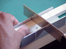
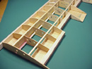
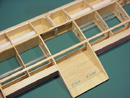
To add strength, 1/32 balsa shear web sheets were added in rear of the spars (photo #16). I skipped the boom when adding the shear webs to gain access to the servo extension cables. The plywood boom support mount were supported by balsa doublers. The leading edge will be trimmed after the top sheeting is glued (photo #17). 1/8 plywood was added between the spars adding strength to the center section (photo #18).
|
|
|
|