 This is the original 3T-GTEU EFI, completely analog, manufactured by
Nippondenso, based on the Bosch L-Jetronic.
The control unit is mounted behind the blower duct, above passenger's
feet. The knock control unit should also be around there, on the right side of passenger's feet.

This sensor is of the flap-type. It measures the air entering the engine (assuming no intake leaks).
When the flap is totally closed, meaning no air is entering the engine, fuel pump is not running. This is achieved by a switch connected to the flap, which connects the fuel pump ground (connector FC) to chassis ground (E1) only when it is open at least partially.
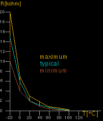
Air temperature sensor is the third function the whole air flow meter
serves, this is a standard automotive NTC resistor (connector THA).
Here's the resistance curve:


Grounds the cold-start injector for 5-12 seconds after starting.

The throttle switches are mounted on the throttle plate axle, and
in this case only have three possible outputs, idle (connector IDL),
wide open throttle (connector PSW) or neither. Connector TL provides
the voltage which the switches deliver to IDL or PSW when closed.

The EFI itself uses 2 pressure switches. First one is used for
enrichment (connector PE) above 0.15 bar (2.2psi) of boost.
This pressure switch measures the pressure through a vacuum line (ok, ok,
it's not in this case always under vacuum) from the intake manifold.
The second pressure switch is for fuel cutoff (connector PC) above
0.5 bar (7.3psi) of boost. This one is measured before the throttle
body. There are two reasons why this does not seem to be a good idea
to keep functioning: the fuel cutoff is not complete, it will
lead to a very lean condition under high load and is BAD for the
engine. It had not caused any damage, but it did render high-speed
drivability to unbearable.


Connector IG.
 Back to Tech Page