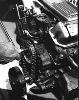
Timing mark alignment

STEP 1. Install the camshaft and timing set. Make sure
that the timing marks on both the cam gear and the crank gear are aligned
per the cam installation instructions.
STEP 2. An example is installing a cam at 102 degrees
intake centerline to achieve 4 degrees of advance. After checking the cam
card specs, install the rocker arms, lifters and pushrods. Set valve lash on the #1 piston. On the
#1 intake lobe adjust the intake lash to zero, being careful not to
preload the lifter. After checking lash, adjust the #1 exhaust lash
to zero and check that both pushrods rolled easily with your fingers.
STEP 3. Fashion a rigid pointer out of an old coat hanger
and attached to the engine block.

STEP 4. With your degree wheel installed on the harmonic
balancer, you are now ready to rotate the engine.
STEP 5. Rotate the crank to get the #1 piston at T.D.C. and check
to ensure both the intake and exhaust valves were closed, then adjust
your pointer to Zero (or T.D.C.) on the degree wheel.
STEP 6. Turn the crankshaft opposite the motor rotation approximately
15-20 degrees. The piston should be lowered enough to allow the T.D.C. stop
to be installed in the spark plug hole. Screw in the piston stop until it
touches the piston. Continue to turn the engine the same direction until
the piston comes back up and touches the piston stop.
Mark (with a felt tipped pen) the number on the degree wheel that
the pointer was on. Rotate the engine in the other direction (motor
rotation) until the piston comes back up and touches the piston stop. Again mark the number from the pointer with your pen.
STEP 7. Remove the piston stop and rotate the crankshaft
to the mid-point of the two marks. This point is T.D.C. for cylinder #1.
Adjust your degree wheel was to read O degrees at the pointer. You cannot
rotate the crankshaft to do this, so unbolt the degree wheel from the
dampner and realign it to read 0 degrees at the pointer. You are now ready
to locate the lobe centerline relative to T.D.C.

STEP 7A. A Dial Indicator may be used to determine TDC, instead of Steps 4-7 above.
STEP 8. Attach the dial indicator to the dial indicator
mount. Set the tip to contact the retainer of the #1 intake valve. Check to make sure that the indicator plunger is parallel to the valve
stem. ** note that any variance in the angle will produce geometric errors
in the lift readings.
STEP 9. Rotate your engine in the normal direction of rotation
until you reach maximum lift. Maximum lift is attained when the dial indicator
changes direction. At this point reset your dial indicator to zero
STEP 10. Rotate the engine in the opposite direction until
the dial indicator reads .100". Turn the engine in the normal
direction until the indicator read .050" before maximum lift. Record the number on the degree wheel.
STEP 11. After that reading, continue to rotate the motor in its
normal direction until the indicator gors past its zero setting to .050"
on the closing side of maximum lift. Again, record the reading.
STEP 12. Add the two numbers and divide by two. This number is the
location of maximum lift of the intake lobe relative to the crank and piston
(a.k.a. the intake centerline). Check your cam spec card and it should confirm
your settings.