|
|
|
|
|
|
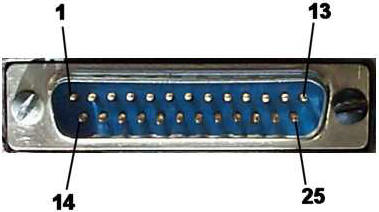
Parallel port is a simple and inexpensive tool for building computer controlled devices and projects. The simplicity and ease of programming makes parallel port popular in electronics hobbyist world. The parallel port is often used in Computer controlled robots, Atmel/PIC programmers, home automation, ...etc. The primary use of parallel port is to connect printers to computer and is specifically designed for this purpose. Thus it is often called as printer Port or Centronics port (this name came from a popular printer manufacturing company 'Centronics' who devised some standards for parallel port). You can see the parallel port connector in the rear panel of your PC. It is a 25 pin female (DB25) connector (to which printer is connected). On almost all the PCs only one parallel port is present, but you can add more by buying and inserting ISA/PCI parallel port cards.
In addition, one input can also be used to create a processor interrupt. This interrupt can be enabled and disabled under program control. Reset from the power-on circuit is also Ored with a program output point, allowing a device to receive a power-on reset when the processor in reset. The input/output signals are made available at the back of the adapter through a right-angled, PCB-mounted, 25-pin, D-type female connector. This connector protrudes through the rear panel of the system, where a cable may be attached. When this adapter is used to attach a printer, data or printer commands are loaded into an 8-bit, latched, output port, and the strobe line is activated, writing data to the printer. The program then may read the input ports for printer status indicating when the next character can be written, or it may use the interrupt line to indicate "not busy" to the software. The output ports may also be read at the card's interface for diagnostic loop functions. This allows faults to be isolated between the adapter and the attached device. =Pin Assignment
=Parallel port registers The Data, Control and status lines are
connected to there corresponding registers inside the computer. So by
manipulating these registers in program , one can easily read or write
to parallel port with programming languages like 'C' and BASIC. =Program This program was written by C language:
|