
Building model railway signalling circuits is like many of the skills required in life, It seems complicated when you dont know how it works. I will attempt to explain some of the circuits I use on my N gauge and OO gauge model railway layouts here in an easy to understand way, if there is such a thing ;) If there is something on this page that doesn't seem to make sense or you know a better way etc, Please let me know and I can update the information held here accordingly. Thank You, Ozz Scott.
There are two main types of `signal controller' circuit, One type uses a Relay, often considered as the old fashioned approach, and the second more modern type uses electronic components (Transistors) to do the switching. Both types of circuit do the same basic job, that is to change which signal lamp is powered according to which reed switch has been activated and hold the signal in that state until a pulse from another reed switch requires it to change. Both methods are quite easy to follow & not much trouble to build, My own preference being for the Relay method, as I happen to have a number of spare `multi-pole' relays in my bits-box, most of which were removed from old computer modems, fax machines and radio equipment that I have scrapped for parts over the years. The relays from even the oldest slowest modems are more than adequate for most model railway signalling & control applications having been made to reasonable standards as required for telecommunications use.

A relay is an electrically operated switch used to allow an electical circuit to turn other circuits on & off, It changes an electrical signal into mechanical movement by energising an electromagnetic coil and attracting or repelling a mechanical switching mechanism, this mechanical movement changes the state of a mechanical switch which is part of the circuit to be controlled.
Relays are most usefull when using one low voltage circuit to control a higher voltage or high current circuit whilst keeping the two circuits isolated from each other. Multi-Pole Relays are used to allow one circuit to control several other circuits by having more than one set of mechanical switches in the relay switched by one electromagnetic coil.
You can have a lot of fun with a few relays, as some of you will already know. If you are unsure of how to use relays it is well worth getting hold of a book of simple electrical circuits and/or one of those `50 in One, Electronic Project Kits' available in high street electrical stores etc, Most people seem to think these are for children, but they can be an invaluable learning tool to anyone making a start in simple electronics or basic electrical circuits. So Go on! have a fiddle with a relay or two, as there are many electrical switching tasks that can be put to very good use on model railways and of course numerous other applications. and you may be glad to hear, most of the circuits for model railways really are simple. Anyone who has looked under a busy model railway baseboard will know just how complicated it can get, but no matter how complex it looks when you break each part of the whole layout wiring down into seperate units each of them is itself quite a simple curcuit. I would suggest signalling a single line section with no junctions or pointwork as a first project, it is then easy to progress onto such things as interlocking the signals with the points, so you set the points, check your signals, take charge of the train, and enjoy it :-).
As there are a great many types of relay available the exact wiring of your circuit will depend on the exact `pinouts' of the relay you are using which may differ from that shown here, the Relays used in the signal controller circuits on this page are Omron `multi pole 12Vdc latching' miniature relays. The `Latching' bit simply means that by feeding power into the relay coil it will change its state to ON in the same way as a normal `non-latching' relay. The latching relay will also lock in the this position and will stay locked ON even when the power feed to the coil is removed. The relay can be switched back off by sending a pulse to the coil in reversed polarity (+ and - round the other way) the relay will then change to and lock in its original position (OFF).
A reed switch is a small magnetically operated mechanical switch, consisting of a sealed glass tube with two reeds held in it, The reeds are made from thin strips of easily magnetised and demagnetised nickel-iron. The switch is operated by bringing a fixed magnet close to the glass tube or by passing a current through a coil surrounding it. the magnetic field of the fixed magnet or coil magnetises the reeds which attract and on touching complete the circuit through the reed switch. The transition time of a reed switch is measured at around One millisecond and there is almost no `contact bounce' (No repeated making & breaking of the circuit when the reeds come together) making them perfect for use in model railway train detection circuits.
This simple method of automatic signalling uses a fixed magnet under each train, I have placed magnets under the leading brake coach of each rake of passenger stock and selected goods stock. Most British N gauge steam locos simply don't have enough space under them to fit a magnet to the locos, although some locomotives with a tender can have the magnet fixed under the tender this is a very fiddly business and is fraught with problems (the tender is better used for additional locomotive power collection from the track), that is why I opted for fitting the magnets to selected rolling stock, which can be fun when marshalling stock as you only want ONE magnet on each train. The magnets fixed to the train operate magnetic reed switches fitted beneath the track, which are used to automatically change the signals as the train enters & leaves the signalled section of track.
Reed switches can only handle a small amount of current and will be damaged if too much current is drawn through them, the reed switches must be protected with a current limiter, which may sound fancy but it is really nothing more than a Resistor.
By placing the reed switches under the track so that when entering the empty signalled section from either end the train triggers the reed switch that sets the relay to power the GREEN signal, as the signal is already at GREEN the relay does not change and you see no effect. Then the train triggers the second reed switch that sets the relay to power the RED signal, The relay obligingly changes over, extinguishes the GREEN signal and shows RED whilst the train continues along the section...
(Fig 01) shows the placement of the reed switches used to detect trains entering & leaving a Bi-Derectional section.
When a train enters the empty section (Signal is at GREEN) from either direction it first passes over the Outermost reed switch, which tries to set the signal to green, as the section was CLEAR and the signal was already at green this does not change the signal. Then the Innermost reed switch is activated which changes the signal to RED showing the section is now occupied.
The train proceeds along the section and may stop within the section, the signal will be held at RED showing the section is occupied until the train leaves the section.
When a train is leaving the occupied section (Signal is at RED) from either direction it passes over the Innermost reed switch, which tries to set the signal to RED, as the signal is already at RED (the Section is still occupied by the train) the signal does not change. Then the train passes over the Outermost reed switch setting the signal to GREEN showing the section is now clear
This method worked well on the single line tunnel section `Casle Hill Tunnel' on the Stoneybridge Railway, which could be worked in either direction with the signalling operating automatically, this also allowed for `shunting' operations to extend into the tunnel, train reversal within the tunnel section and the train leaving the section from the direction it entered it. (See FIG 02)
On tracks that are `visible' (in the scenic area) ond operate in ONE direction only, IE, one track of a double track mainline, The reed switches can be placed within adjacent sections to allow an for an `overlap' or `Overrun' area beyond each signal. The exact distances can be adjusted to suit the specific local track plan of your layout. (See FIG 03)

Reed switches are `Polarised' in that they will only react to a magnetic field that is in the correct orientation to the reeds in the switch, and does not react to magnetic fields oriented 90 degrees from this operating position, this makes train Type detection easily possible. (See Fig 04.)
All trains have one magnet (to activate the signalling circuits) and only stopping services have the second magnet fitted, so that as the `stopping service' train approaches a station the train Type detector circuit is used to set the signals to red and stop the train. All other trains (single magnet) will of course proceed through the station operating the block section signalling as normal, unless the operator takes over control of the train or signals manually to allow for out of sequence train movements in the station area such as pilot locos on shunting duties.
A Train Type Detection circuit can be used in this way to automatically set points, signals or whole routes dependant on the type of train entering a section of track.
Most of you will be able to build your own signalling circuits but there will be a few of you who may not be able to build such things yourselves due to fading eyesight, a disability, or simply a dislike of "electrics" You may be able to get someone you know to build the fiddly bits for you, If not and you are stuck, there is an alternative to building it yourself..
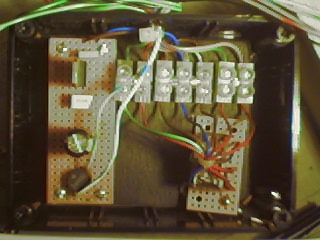
This `control box' and one of the two signals it operates were built by Tony Giddings, a local modeller who also designs & makes other usefull `devices' for his Ngauge layouts.. Tony can be contacted at, 93 Galloway Road, Hamworthy, Poole, Dorset, England, BH15 4JC. Sorry, but Snail Mail is the only way to contact him, the Phone is no good as he is deaf, Tony also suffers from a slight palsy (shakes) occasionally but he has built a few of these automatic signal units for my Stoneybridge West layout and all have been to a much higher standard than I could manage myself!. :-)
The Automatic Signal Controller Unit (Relay box) shown here is used to protect the Down line through the tunnel under Stoneybridge Town, it is an easy circuit using a Latching Relay and Magnetic Reed Switches operated by a magnet fixed under the train which allows for automatic bi-directional 2 aspect signalling of a single line or any section of double line that is to be worked in both directions or shunted from either end. The small board on the Left of the control unit shown here is a simple power conversion board, with a bridge rectifier, which turns AC (alternating Current) into DC (Direct Current) and a voltage regulator, to ensure a steady 12Volt DC output. The small circuit board to the bottom right of the picture holds a latching relay and the `chocolate block' connection strip allows easy connection of longer cables if required.
