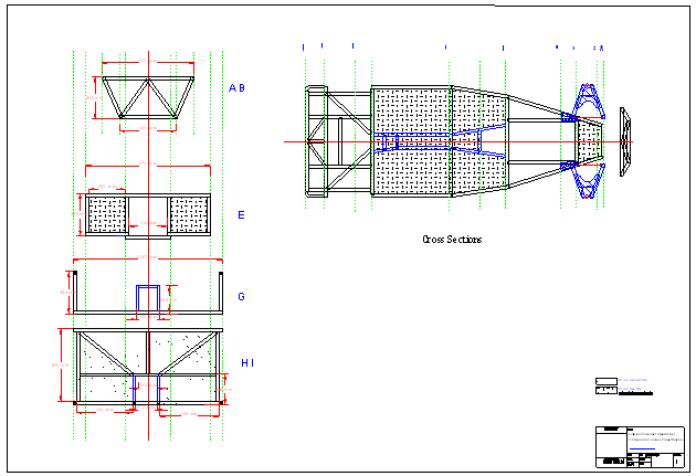


Chassis Design
As the standard chassis wont pass the Australian torsional
tests we had modify our chassis design to increase the rigidity.
After a lot of reviewing of the maillist and many a late night being
creative on Turbo CAD I came up with the following modifications
to the standard chassis:
* Widening of the complete chassis by 100mm
- to allow more room for people, engines, geearboxes and to make
the car appear lower and wider.
* Triangulation of the front face of the chassis
- to strengthen the front face of the chassiis.
* Additional bracing of the engine bay to both top and bottom
plans
- to strengthen the engine bay, which appearrs to be a weak area (torsionally).
A second R tube on the other side appears to make a considerable
difference to torsional rigidity.
* An additional crossbrace at the top, front of the engine bay
between the rear mounts of the top wishbones
- I may have to make this removeable to get the engine in!
designed to strengthen the front suspension framework.
* Additional diagional bracing from the engine mount area up to
the top, rear wishbone mounts
- I understand that this is a requirement for all the Oz chassis.
designed to strengthen the engine bay/ engine mounting area.
* Increased bracing of the rear section to accommodate the future
capacity to tow a small trailer of <250kg.
- I saw this on Les Newell's website and thoought that it was a
Great idea! A cute little box trailer would be very useful for
country trips or race meetings. Next project?
* Steel floor, firewall, transmission tunnel sides and outer body
sides for improved strength and safety.
- side intrusion protection is required for all Oz chassis and
its just as easy to weld the steel plate as rivet the Ali plate,
so I decided to use steel all around the passenger compartment -
side intrusion, trans tunnel, floor pan, firewall.
* Raising the rear suspension/ rollbar mount by 50 mm and
therefore angling the top of the rear section rearwards and down
by 50mm.
- this is purely for asthetic reasons. From looking at lots of
pictures it seems that having the rear top rail (behind the
driver's head) at the same height as the scuttle looks better and
allows a bit of slope back and down to the top, rear edge of the
car.
* Lowering the rear point of the ‘horizontal’ section
which makes up the ‘doorway’ by 50mm
- again for asthetic reasons to more resemblle the original.
* Moving the vertical section to which the rear trailing arms
attach, forward by approximately 25mm.
- this is the vertical tube that the trailinng arms attach to. By
moving it slightly forward, it again supports the top horizontal
tube (which is now angled down by 50mm) and slightly lengthens
the trailing arms.
* Continuing the bottom outer chassis rail rearwards and
horizontal until behind the rear drivetrain
- this provides more room for the rear axle to droop.
Go to the Pictures page to see pics of the chassis construction.