If you want to ask me any questions, you can reach me at pocher_rolls@yahoo.com.
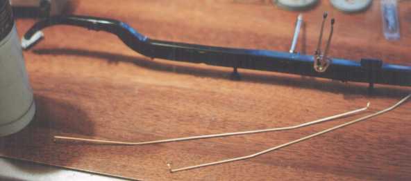
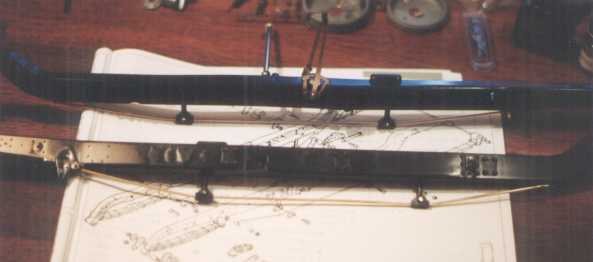
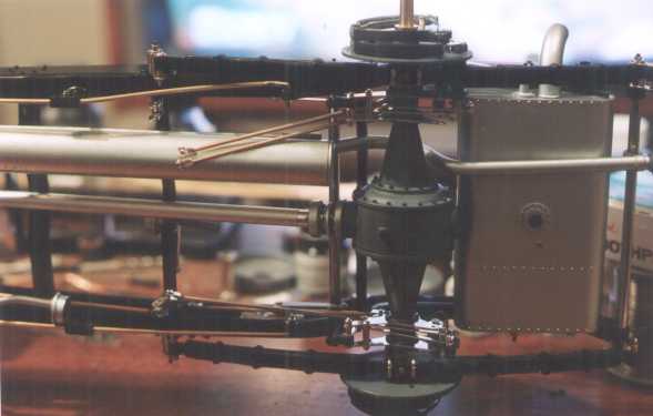
Now it was time to prepare the frame rails for accepting the individual sub-assemblies. The step shown here was to attach the truss rods. Great if they were long enough. They were a hair short before being bent into the proper shape to fit into the truss rod support mounts. After bending, they would wind up even shorter.
I was almost in a panic until I remembered that brass is soft and is easily heated with a torch. So, I broke out with the ol' butane torch, heated the rods and stretched them about1/8 inch. After stretching, I bent them into the proper shape. In the left-hand part of the photo below, you can see the can part of the torch.
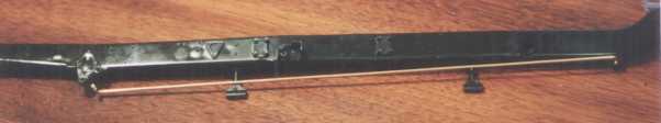
Here they are, all nicely installed and ready for the next step
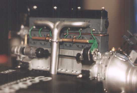
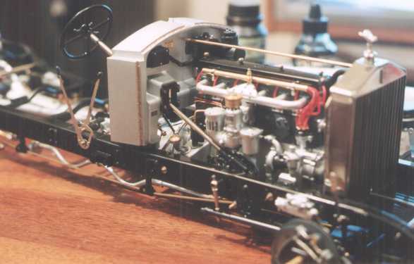
While doing all these other assemblies, I still had the thought of the sparkplug wire tube on the exhaust side of the engine in my mind. After having seen the photos of the engine of an actual car (go back to Page 2), I wanted to make my modification look like the real thing before I installed the engine into the frame. So, I did. I shortened the tube by one hole and painted the magneto.
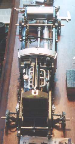
Ok, Back to the frame. This was one of the more involved assemblies mainly due to the lack of clear instructions (or the instructions had not been thoroughly thought out). They pretty much say to start at the front and work your way back. They also say to attach the leaf springs onto the frame rails then attach the axles. That didn't seem to make sense since the engine/transmission assembly (a fragile assembly mind you) was to be attached to the frame early on and the other assemblies attached later expecting you to keep from damaging the engine/transmission. Also, the screws and nuts used to attach the axles to the springs would be harder to get at if the springs were attached to the frame rails first. I figured I would start from the back and work my way forward.
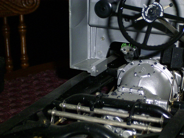
Well, I quickly discovered that this wasn't going to work very well. I read over the Boyd Models supplement instructions for this kit and their approach seemed to make more sense and was clearer except for the installation of the axles and suspension, which I did differently, and the firewall. They say to attach the springs to the frame rails and add the firewall and axles after the frame was assembled. That's all fine and dandy if the steering wheel hadn't already been attached to the end of the steering column assembly per the instructions earlier on. I carefully attached all the subassemblies (except the springs and axles) and cross-members onto one frame rail (making sure that those parts that would need to move and/or rotate freely could do so) then attached the other frame rail to complete the assembly. After that was done I attached the axles which already had the suspension attached to them. I figured that putting in the rear axle after the engine was secured in the frame would allow for better adjustment of the drive shaft if necessary, which it was. The drive shaft turned out to be too long. No problem, just shorten part of the end of the plastic shaft that fits into the plastic bushing that's in the transmission end of the drive shaft. Then the firewall was attached. Well, the assembly of the frame sounds simpler than it really was. I ran into more problems than I can recall assembling this frame. To make a long story short, I had to dismantle some assemblies to install them and other assemblies, then reassemble them after they were attached to the frame, then disassemble some of them again for some other reason, etc. I spent about two weekends and five evenings putting this thing together. Part of the reason it took so long was I missed a part or two that required me to pull one of the frame rails off and put everything back again. The firewall and steering components are a good example. When you go to install the firewall onto the frame, you quickly discover that this would be much easier if the steering column were not installed yet. And, don't forget to install the steering mechanism onto the frame before you install the engine. The firewall is attached by sliding the lower edge of the cowl into the recess of the two different mounting blocks (one with two holes, one with three), then screwing the mounting blocks onto the frame.
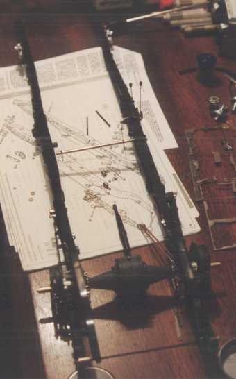
I won't EVEN get into the various fit problems. When you try this, I suggest you gather all your pieces and subassemblies and spread them out over an entire table (the bigger the better) and take inventory at least twice before starting the assembly. Actually lay out ALL the pieces (screws, nuts, break rods, etc.) on the table the way they would be placed on the frame so you can see where you will have to make adjustments in the assembly procedure. It's better to spend the time doing this and assemble the frame once rather than experiencing the frustration of disassembling and reassembling several times. I keep some of my coworkers updated on the progress I make by starting out with "the continuing story of the Pocher..." One of my coworkers told me "it's not a story anymore, it's a Saga."
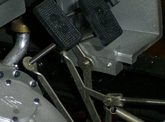
After I had it together (or so I thought) I started attaching the break linkage. I figured I would start with the rear breaks since they were more difficult, that way, the front would seem relatively easy (yeah, right).
Time for an all-new set of problems.
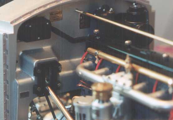
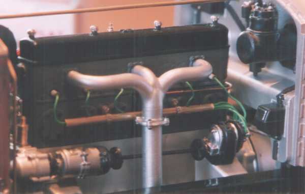
The rear breaks didn't want to function properly from the pedal (like that's a surprise). I got the parking break to work but not to my satisfaction. I've spent several weeks (off and on) on the breaks and still haven't worked out all the problems. I've actually removed the rear axle assembly and started to re-work the rear break assembly and the axle housing. I'm determined to make the brakes functional. The owner's handbook shows that some of the break rods aren't rods but cables. I'm thinking about recreating the cables and seeing if they will work better than the rods supplied by Pocher. Here go two views of the engine as it now sits in the frame.