 and a series of big bikes with the latest as a Yamaha R1
  which only wants to do this
PHOTO PAGE
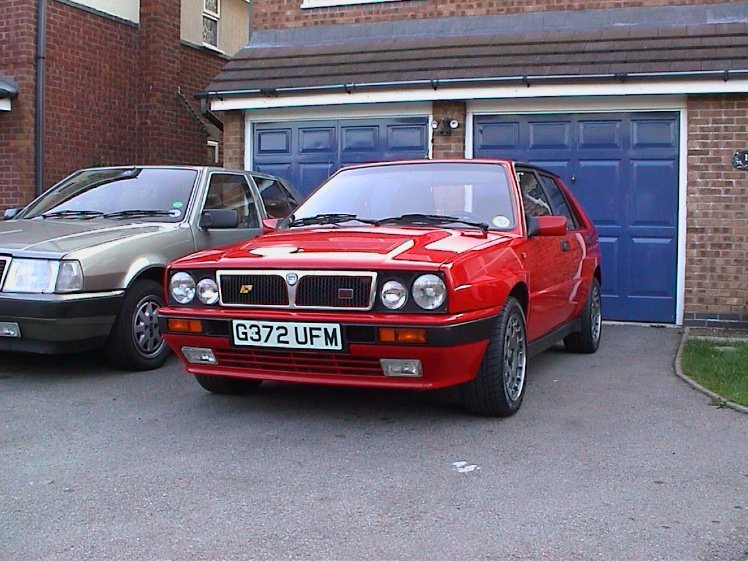
So why a Dax Rush Quadra? Well
after having one of these
and a series of big bikes with the latest as a Yamaha R1
which only wants to do this
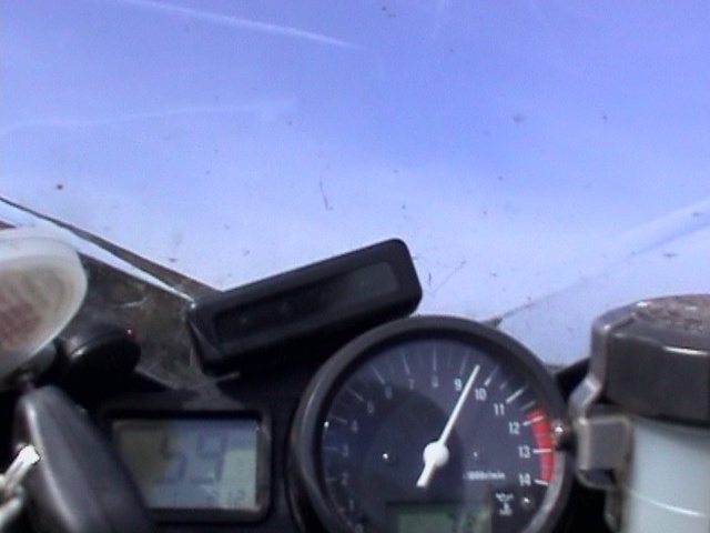 every time you open the throttle!! It only
took the Quadra 0-60 in 3.15s demonstrated time and I was there!
every time you open the throttle!! It only
took the Quadra 0-60 in 3.15s demonstrated time and I was there!
(Go to Page 2 to see the finished article)
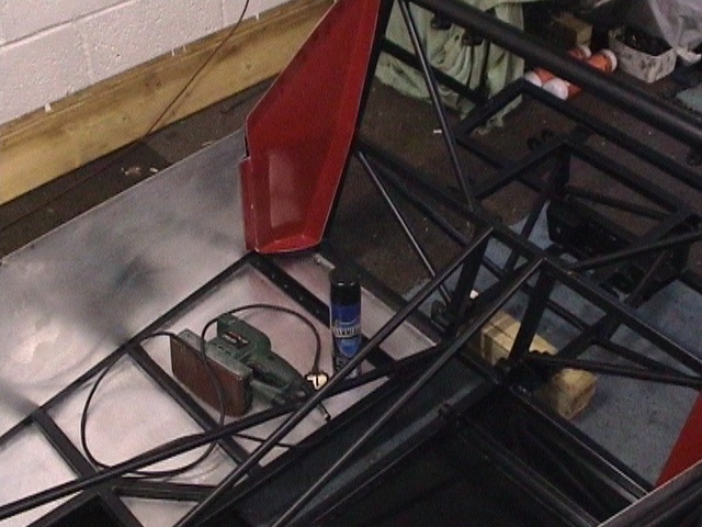
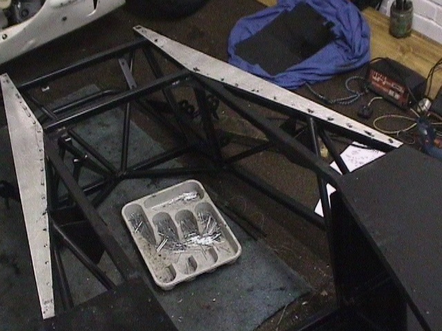
I started in April 2000 and spent about 18 months worth of weekends and evenings including donor vehicle parts reconditioning:-
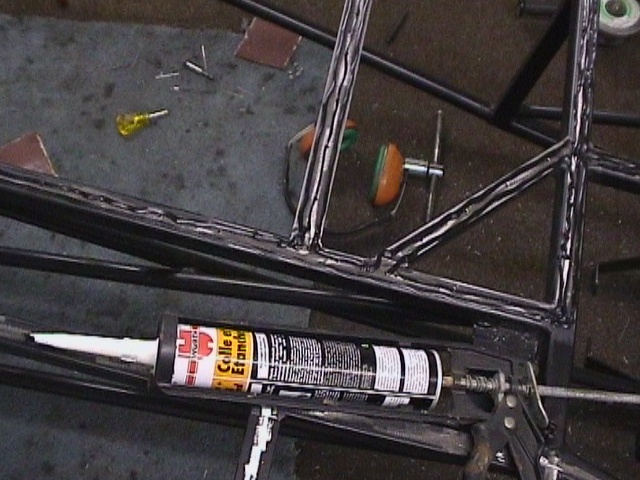
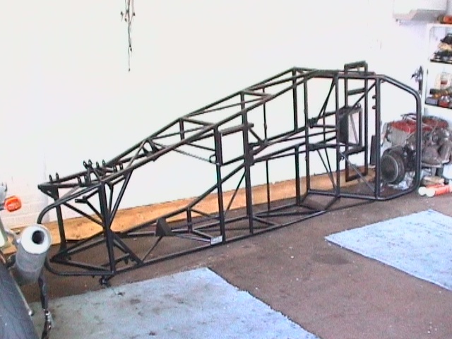 All
welds were under sealed for extra corrosion resistance.
All
welds were under sealed for extra corrosion resistance.
 centre punched and drilled
every 2 inches
centre punched and drilled
every 2 inches
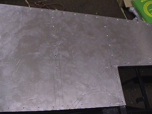 secured with 5 self tappers
for drilling chassis
secured with 5 self tappers
for drilling chassis
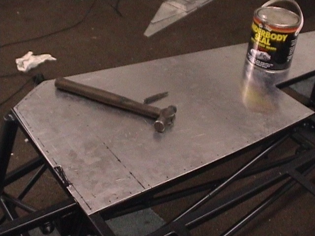
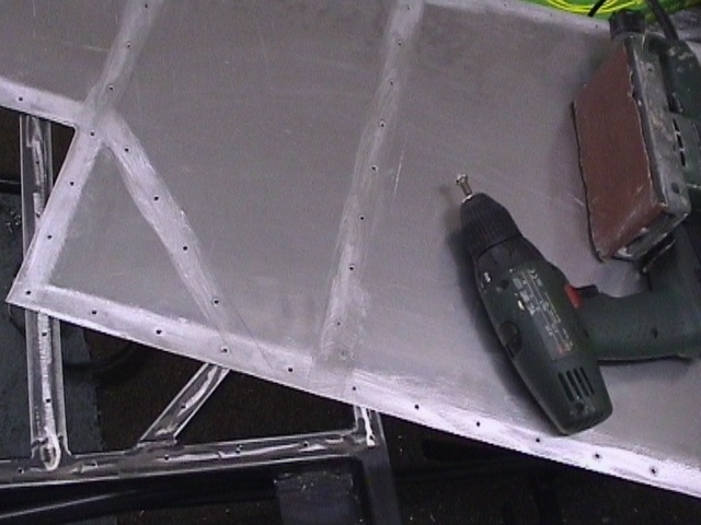 deburred all holes and sanded interfaces
 front infill panels can also
be done at this stage
front infill panels can also
be done at this stage
 relocated
with 5 self
tappers & rivets dipped in Wurth
relocated
with 5 self
tappers & rivets dipped in Wurth
 rear sides need positioning
by sides and rear panel
rear sides need positioning
by sides and rear panel
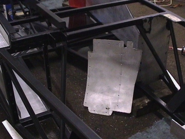 front bulkheads needed a
mild bend to assemble
front bulkheads needed a
mild bend to assemble
 chassis rails marked on rear
panel for hole positions
chassis rails marked on rear
panel for hole positions
 rear panel held again by
self tappers while drilling
rear panel held again by
self tappers while drilling
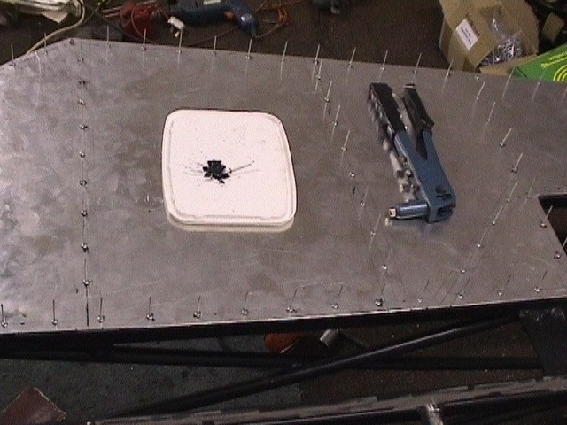
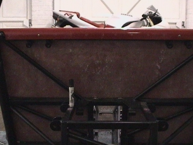 rivets were later
removed as visible above the boot
rivets were later
removed as visible above the boot
 side panels fixed last
 large head rivets for GRP
 front infill panels
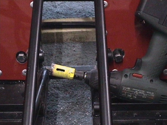 27mm box drill gives access
to lower wishbone bolts
27mm box drill gives access
to lower wishbone bolts
 Bushes
into chassis for diff mounting
Bushes
into chassis for diff mounting
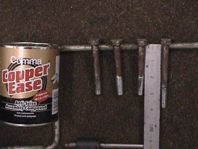 Diff
mounting bolts are three 3 inch & one 4 inch
Diff
mounting bolts are three 3 inch & one 4 inch
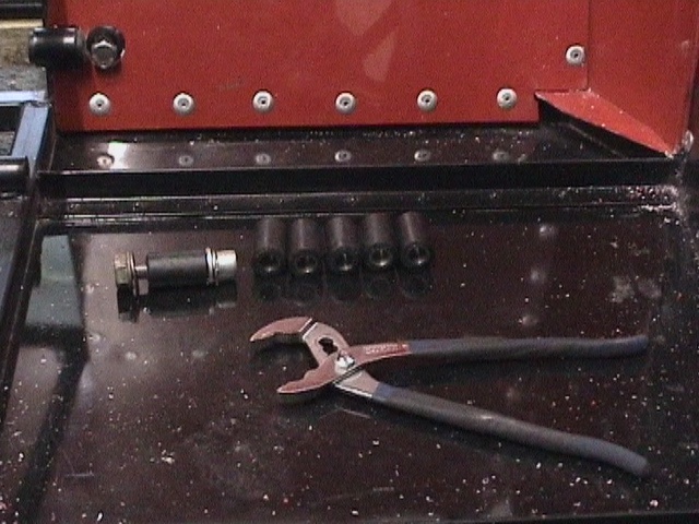
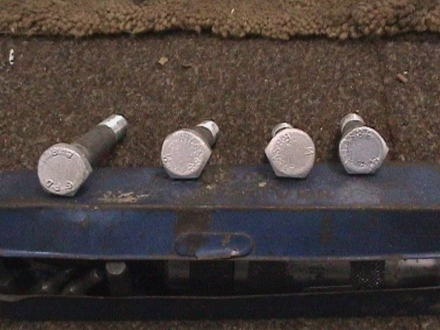 3
corners ground off bolts fitting into diff
3
corners ground off bolts fitting into diff
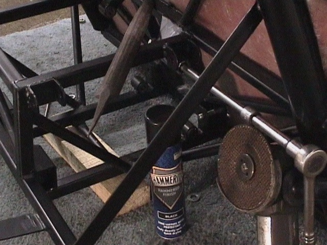 Upper
wishbone support may need relieving for socket
Upper
wishbone support may need relieving for socket
 Diff
needed lightly jacking to fit last lower front bolt
Diff
needed lightly jacking to fit last lower front bolt
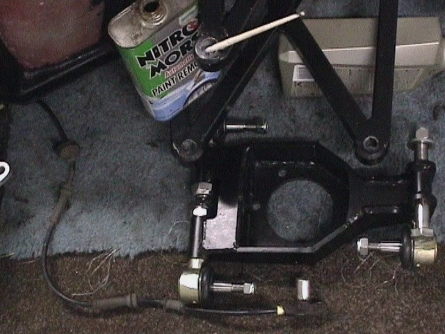
 rear
upright trial assembly
rear
upright trial assembly
 pitch
of ball joints needs to = pitch of tapered holes in wishbone
pitch
of ball joints needs to = pitch of tapered holes in wishbone
 material
removed equally from both sides evenly
material
removed equally from both sides evenly
 paint
removed from tapered holes
paint
removed from tapered holes
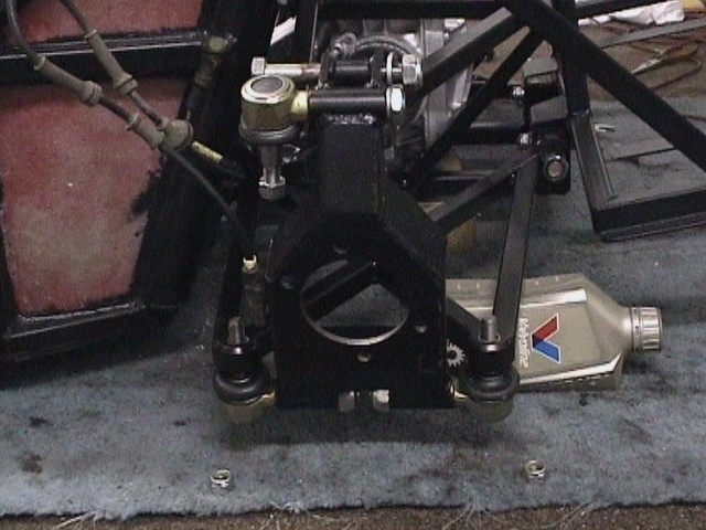 when
the pitch of the ball joints is correct the weight of the upright can be
supported by the ball joint tapers alone
when
the pitch of the ball joints is correct the weight of the upright can be
supported by the ball joint tapers alone
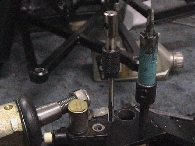 for
the ABS sensor mounting features (Sierra front ones for Rush rear) a 17mm box
drill and 6mm tap were used
for
the ABS sensor mounting features (Sierra front ones for Rush rear) a 17mm box
drill and 6mm tap were used
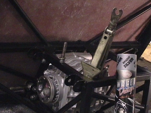
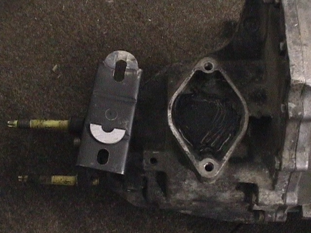 standard
gearbox mount required hole extensions to fit 4x4 MT75
standard
gearbox mount required hole extensions to fit 4x4 MT75
 cutting
the gearbox mount in half and shortening lowered the gearbox by some 15mm
cutting
the gearbox mount in half and shortening lowered the gearbox by some 15mm
 The engine mount studs were cut down in length to ease assembly to the chassis.
The middle starter motor mounting bolt hole was relieved to 8mm to clear the
chassis.
The engine mount studs were cut down in length to ease assembly to the chassis.
The middle starter motor mounting bolt hole was relieved to 8mm to clear the
chassis.
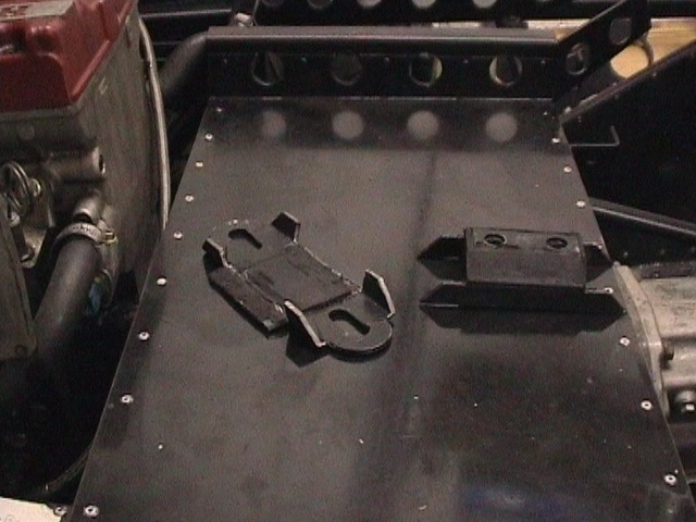
 reassemble
gearbox mount which also needed quality nuts bonding in position with HV350
reassemble
gearbox mount which also needed quality nuts bonding in position with HV350
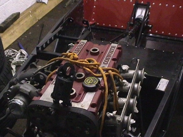 Trial
fit of engine
Trial
fit of engine
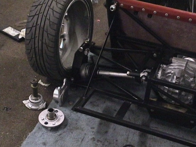
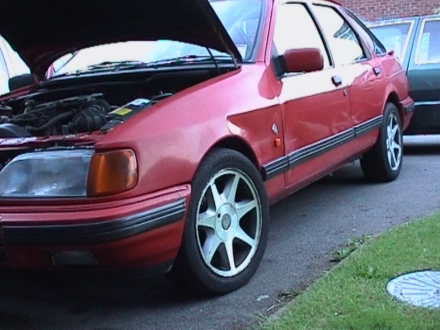 Good
old Sierra Donor vehicle supplied steering column, front and rear hubs and
transmission, brakes and of course ultimately Cosworth Engine and gearbox!
Good
old Sierra Donor vehicle supplied steering column, front and rear hubs and
transmission, brakes and of course ultimately Cosworth Engine and gearbox!
 This
one even came fitted with Brooklands 16x7 wheels.
This
one even came fitted with Brooklands 16x7 wheels.
 Front
diff ONLY needed new output bearings and seals
Front
diff ONLY needed new output bearings and seals
 be
sure to mark positions of bearing cups before disassembly
be
sure to mark positions of bearing cups before disassembly
 27mm
box drill & 1/2 inch 1/4 drive socket used to produce cut out in dust shield
27mm
box drill & 1/2 inch 1/4 drive socket used to produce cut out in dust shield
 50mm
socket used to drift new bearings in front upright
50mm
socket used to drift new bearings in front upright
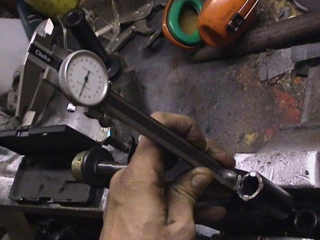
 riveted
pawl from Sapphire throttle pedal welded on to Dax throttle lever shortened by
37mm allows the use of a standard throttle cable
riveted
pawl from Sapphire throttle pedal welded on to Dax throttle lever shortened by
37mm allows the use of a standard throttle cable
 top
end of Sapphire brake pedal welded on to Dax pedal
top
end of Sapphire brake pedal welded on to Dax pedal
 Dax
pedal box modified to accept Sapphire master cylinder
Dax
pedal box modified to accept Sapphire master cylinder
 the
original master cylinder mounting flange was spaced to give 130 to 140mm back
from pedal box axis
the
original master cylinder mounting flange was spaced to give 130 to 140mm back
from pedal box axis
 master
cylinder axis 60mm above pedal box axis
master
cylinder axis 60mm above pedal box axis
 Mountney
12 inch steering wheel may still need extra foam for some SVA test stations
Mountney
12 inch steering wheel may still need extra foam for some SVA test stations
 2
plastic bushes used to seal hole in front bulkhead
2
plastic bushes used to seal hole in front bulkhead
 steering
column shorted to 210mm from plastic bush
steering
column shorted to 210mm from plastic bush
 thick
end of lower steering column shortened by 45mm
thick
end of lower steering column shortened by 45mm
 thin
end of lower steering column shortened by 70mm
thin
end of lower steering column shortened by 70mm
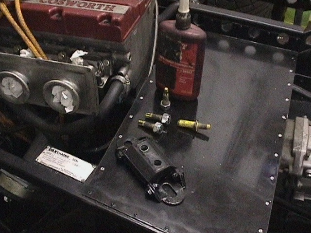
 internal
components of master cylinder reservoir. 2 were required to make all the
necessary remotes and adaptors
internal
components of master cylinder reservoir. 2 were required to make all the
necessary remotes and adaptors
 3
inch diameter Mongoose stainless header pipe needed a 20mm segment removing to
increase bend
3
inch diameter Mongoose stainless header pipe needed a 20mm segment removing to
increase bend
 stainless
tubes were welded inside and out to produce 6mm rim for SVA
stainless
tubes were welded inside and out to produce 6mm rim for SVA
 a
new bracket was required with captive bolts to hold the ABS valve block
a
new bracket was required with captive bolts to hold the ABS valve block
 ABS
valve block fitted in front of drivers front bulkhead
ABS
valve block fitted in front of drivers front bulkhead
 back
brake piping is standard Rush with the brake light switch acting as the rear
T-piece
back
brake piping is standard Rush with the brake light switch acting as the rear
T-piece
 some
4m of extra copper pipe are needed for the ABS system
some
4m of extra copper pipe are needed for the ABS system
 Draper
flaring tool needed deburring to prevent excessive pipe marking. Better brake pipe flaring
tools are available without threaded pipe holders.
Draper
flaring tool needed deburring to prevent excessive pipe marking. Better brake pipe flaring
tools are available without threaded pipe holders.
 after
deburring a double flare was best produced with about 5mm of pipe protruding
after
deburring a double flare was best produced with about 5mm of pipe protruding
 the
flaring die had to remain perpendicular all the way through flaring to produce
an even flare
the
flaring die had to remain perpendicular all the way through flaring to produce
an even flare
 material
removed from standard 2wd Rush gearbox tunnel to modify for 4wd gearbox
material
removed from standard 2wd Rush gearbox tunnel to modify for 4wd gearbox
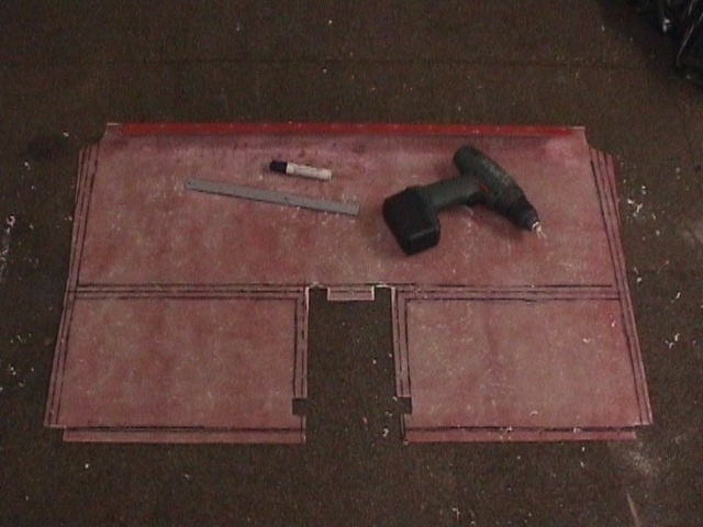
 cardboard
cutouts were used as patterns for the tunnel and tunnel sides
cardboard
cutouts were used as patterns for the tunnel and tunnel sides
 a
90mm bend line gave maximum clutch pedal clearance
a
90mm bend line gave maximum clutch pedal clearance
 3D
shape formed with a rubber mallet
3D
shape formed with a rubber mallet
 throttle
pedal was bent out to give more clearance to the brake pedal
throttle
pedal was bent out to give more clearance to the brake pedal
 drivers
side cover domed out for more foot clearance
drivers
side cover domed out for more foot clearance
 reservoir
parts modified and made using M10 cap head bolts
reservoir
parts modified and made using M10 cap head bolts
 assembles
3 port remote reservoir
assembles
3 port remote reservoir
 final
exhaust bracket was bolted to the chassis cross member
final
exhaust bracket was bolted to the chassis cross member
 the
pedal box was dropped a further 8mm by cutting from support bases to give better
brake hose to scuttle clearance
the
pedal box was dropped a further 8mm by cutting from support bases to give better
brake hose to scuttle clearance
 Teflon
pipe came from Earl's at Silverstone
Teflon
pipe came from Earl's at Silverstone
 front
master cylinder port uses internal 3/16 copper pipe running inside the Teflon front hose for bypass flow
front
master cylinder port uses internal 3/16 copper pipe running inside the Teflon front hose for bypass flow
 scuttle
clearance was only just achieved
scuttle
clearance was only just achieved
 an
extra bracket is needed for the front mount of the high pressure pump
an
extra bracket is needed for the front mount of the high pressure pump
 more
material had to be removed from the pedal box to give clearance for the
accumulator
more
material had to be removed from the pedal box to give clearance for the
accumulator
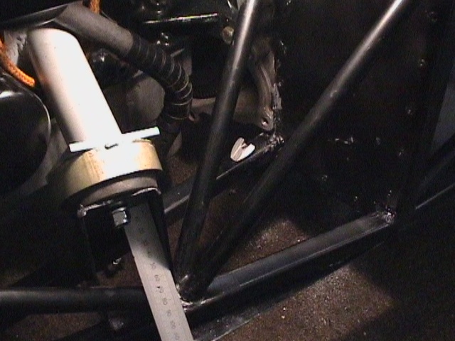
 the
high pressure pump uses the standard rubber bushes for vibration damping
the
high pressure pump uses the standard rubber bushes for vibration damping
 with
the petrol tank exit shortened by 20mm and bent round 40°, only a 6 inch hose
is needed to join to the pre-pump filter
with
the petrol tank exit shortened by 20mm and bent round 40°, only a 6 inch hose
is needed to join to the pre-pump filter
 a
rubber grommet at a height of 40mm as far to the left as possible allows the
fuel line to pass through the lower chassis
a
rubber grommet at a height of 40mm as far to the left as possible allows the
fuel line to pass through the lower chassis
 one
Terry clip with a tie strap was used to secure the fuel filter
one
Terry clip with a tie strap was used to secure the fuel filter
 fuel
lines passing around the inside of the LHS chassis rails meant another gearbox
tunnel extension
fuel
lines passing around the inside of the LHS chassis rails meant another gearbox
tunnel extension
 more
cardboard cut outs for shields to go inside the pedal box area
more
cardboard cut outs for shields to go inside the pedal box area
 an
ali sheet box to cover the outside of the pedal box
an
ali sheet box to cover the outside of the pedal box
 rubber
grommets used to take the Teflon pipes through the pedal box cover
rubber
grommets used to take the Teflon pipes through the pedal box cover
 final
layout of pedal box internals
final
layout of pedal box internals
 dome
produced in pedal box cover to give 4mm clearance to the accumulator
dome
produced in pedal box cover to give 4mm clearance to the accumulator
 a
view inside the scuttle
a
view inside the scuttle
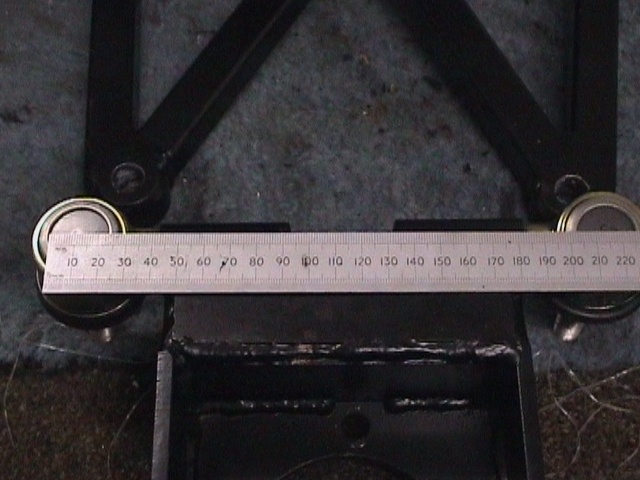
 the
handbrake cable passes through the tunnel some 260mm from the front of the
tunnel and 35mm in from the edge
the
handbrake cable passes through the tunnel some 260mm from the front of the
tunnel and 35mm in from the edge
 both
sides of handbrake cable ends needed relieving to 14mm to pass through chassis
lugs
both
sides of handbrake cable ends needed relieving to 14mm to pass through chassis
lugs
 as
there was no groove in one side of the handbrake cable the shoulder was relieved
by 2mm to fit an R-clip
as
there was no groove in one side of the handbrake cable the shoulder was relieved
by 2mm to fit an R-clip
 Sierra
front ABS sensor fitted to Dax rear upright with ultimately 0.7mm shimming to
give a 0.2mm clearance to the grooved CV housing
Sierra
front ABS sensor fitted to Dax rear upright with ultimately 0.7mm shimming to
give a 0.2mm clearance to the grooved CV housing
 assembled
rear hub
assembled
rear hub
 a
Lucas 115 alternator using an 850mm Escort fan belt
a
Lucas 115 alternator using an 850mm Escort fan belt
 a
shorter oil filter allows room for the throttle assembly
a
shorter oil filter allows room for the throttle assembly
 reducing
the area of the gasket increases its surface pressure and reduces the chances of
a leak
reducing
the area of the gasket increases its surface pressure and reduces the chances of
a leak
 the
base of the throttle cable pillar was cut off and welded back on at 90°
allowing it to bolt on to two convenient holes on the block
the
base of the throttle cable pillar was cut off and welded back on at 90°
allowing it to bolt on to two convenient holes on the block
 Sierra
XR4x4 ABS loom re-wrapped to suit Rush installation
Sierra
XR4x4 ABS loom re-wrapped to suit Rush installation
 Cosworth
Engine harness re-wrapped to move idle speed control valve lead back a foot from
the 3rd injector
Cosworth
Engine harness re-wrapped to move idle speed control valve lead back a foot from
the 3rd injector
 Speedo
pickup was taken from the inner CV as the ABS sensors were reading the outer CV
Speedo
pickup was taken from the inner CV as the ABS sensors were reading the outer CV
 extra
sheet from the turbo blanket was used for heat insulation on the gearbox tunnel
sides and air filter box
extra
sheet from the turbo blanket was used for heat insulation on the gearbox tunnel
sides and air filter box
 a
70mm long rigid steel bracket was used to support the speedo sensor
a
70mm long rigid steel bracket was used to support the speedo sensor
 The
Dax front prop shaft supplied by GKN in Leek may be cheaper sourced from
somewhere like Prop Tech in Kidderminster
The
Dax front prop shaft supplied by GKN in Leek may be cheaper sourced from
somewhere like Prop Tech in Kidderminster
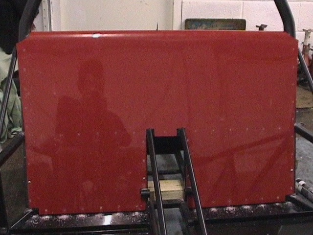
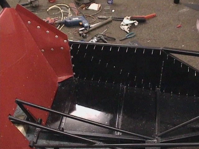
 rear
tub fitted to 410mm dimension on drawing
rear
tub fitted to 410mm dimension on drawing
 side
panels needed some trimming to accept rear tub
side
panels needed some trimming to accept rear tub
 large
rivets were removed (leaving Wurth underneath) from the back of the rear
bulkhead as they were visible above the boot tub. The fuel cap breather was
reduced in length by 30mm
large
rivets were removed (leaving Wurth underneath) from the back of the rear
bulkhead as they were visible above the boot tub. The fuel cap breather was
reduced in length by 30mm
 The
universal Spec-R oil separator tank was modified to keep the height inside 220mm
The
universal Spec-R oil separator tank was modified to keep the height inside 220mm
 a
3/8x19 bsp tap and a 15mm tapping drill were used to make thread to accept the
crankcase breather adaptor. This was bonded in with HV350
a
3/8x19 bsp tap and a 15mm tapping drill were used to make thread to accept the
crankcase breather adaptor. This was bonded in with HV350
 cutting
a thread in a steel plate allowed the same 3/8x19 bsp thread to be cut on to the
Amber Performance sump return tube
cutting
a thread in a steel plate allowed the same 3/8x19 bsp thread to be cut on to the
Amber Performance sump return tube
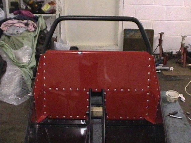
 side
panels require some 23mm reduction in top length to allow them to mate up to
rear tub
side
panels require some 23mm reduction in top length to allow them to mate up to
rear tub
 the
thermostat housing right angle exit was cut off and an ali rim MIG welded on to
the end of the remaining pipe
the
thermostat housing right angle exit was cut off and an ali rim MIG welded on to
the end of the remaining pipe
 various
synthetic oils used for gearbox, transfer box, engine and differentials. Plan to
use Motul 300v 15W50 at first oil change
various
synthetic oils used for gearbox, transfer box, engine and differentials. Plan to
use Motul 300v 15W50 at first oil change
 Dax
supplied foam used to edge fan radiator mounting
Dax
supplied foam used to edge fan radiator mounting
 battery
shelf and side panel needed relieving to fit
battery
shelf and side panel needed relieving to fit
 a
cut line was drawn on perpendicular to the base of the side panel running
through the centreline of the scuttle winged piping
a
cut line was drawn on perpendicular to the base of the side panel running
through the centreline of the scuttle winged piping
 L-sectioned
ali brackets were bonded using HV350 to the leading edge of the cut side panel
L-sectioned
ali brackets were bonded using HV350 to the leading edge of the cut side panel
 winged
piping was bonded using HV350 to the L-sectioned ali brackets
winged
piping was bonded using HV350 to the L-sectioned ali brackets