![]()
![]()
![]() @DréCB/19MIR000=27.805Mhz./USB&6635Khz./LSB][SoundFM90.7-FM90.7Mhz.@
@DréCB/19MIR000=27.805Mhz./USB&6635Khz./LSB][SoundFM90.7-FM90.7Mhz.@
![]()
![]()
YAGI ANTENNA 4 ELEMENTS
for
PMR446
Info by Per
Some people have replaced the fixed antenna on their PMR equipment with a coaxial connector which allows them to use external antennas
instead.
I will in the following describe a four element Yagi antenna I designed and built for the PMR band, it is a real low cost design and easy to put together.
The goal was to make a design that
require not to much experience and use of ordinary tools possible to find in
almost every household, as an example, there is no need for a drilling machine.
The tools needed are ;
- Hammer
- Folding rule or
equivalent
- Pencil
- Hacksaw
- Knife (to cut the
coax cable)
- Soldering
iron
- And a small
amount of glue.
| Number | Type | Dimension | Length | Remarks |
| 1 | Wood Strip | 21 x 15 | 600 | Boom |
| 4 | Wood Strip | 21 x 8 | 100 | Support |
| 8 | Nails | |||
| 1 | Aluminum Tube | Ø12 | 326 | Reflector |
| 2 | Brass Tube | Ø12 | 150 | Driver |
| 1 | Aluminum Tube | Ø12 | 271 | Director 1 |
| 1 | Aluminum Tube | Ø12 | 261 | Director 2 |
| 16 | Plastic Strip | Min 120 |
The antenna consist of a wood frame, see figure 1. The dimension used is not critical, I used two different dimension of wood strip, boom
dimension is 21 x 15 and the four supports is 21 x 8. The frame is glued and nailed together. The supports shall be mounted in right angle to the
boom, see figure 1 and
2.
When you are ready with the frame it has to be painted. It is necessary, because it have not to take up any moister which can affect the
performance of the antenna. You can use a metallic boom instead, but in this design is it necessary to isolate all the antenna elements from the
boom.


To
attach the antenna elements to the Wood frame I used plastic straps, it is easy
and fast, see figure 3, 4, 5.
When
you assembly the driver element leave a gap of 2mm between the two element
halves, see figure 4.


In
this text I will not describe how to split up a coax cable, you can find it some
where else at the web.
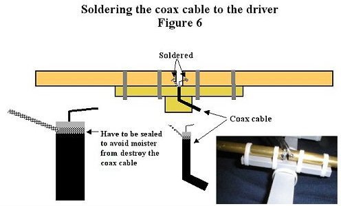
IMPORTANT,
do not forget to seal the coax cable after you have split it up, to avoid it to
take up moister.
Also the solder joints must be sealed, use epoxy, glue, paint
or what else you have in house.
When you solder the coax cable to the two halves of the driver, heat up the tubes first, it takes some seconds for the brass tube to heat up.
Apply a small amount of solder and let it melt before you solder the coax to the tubes. In figure 6 you can see the coax cable connected to
the driver.
In figure 7 you can se the complete antenna. The performance of this antenna is rather good, wide bandwidth with a good match to
50 ohm coax.

Gain:
9dBi
F/B: 11dBi
Information
by ; Per

![]()
![]() @DréCB/19MIR000=27.805Mhz./USB&6635Khz./LSB][SoundFM90.7-FM90.7Mhz.@
@DréCB/19MIR000=27.805Mhz./USB&6635Khz./LSB][SoundFM90.7-FM90.7Mhz.@
![]()
![]()
![]()