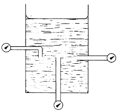
 Figure 2-6.—Pressure of a liquid is independent of direction.
In Fig 2-6 the pressure measured at different positions but at the same depth is always the same.
And The extensive use of hydraulics and pneumatics to transmit power is due to the fact that properly constructed fluid power systems possess a number of favorable characteristics. They eliminate the need for complicated systems of gears, cams, and levers. Motion can be transmitted without the slack inherent in the use of solid machine parts. The fluids used are not subject to breakage as are mechanical parts, and the mechanisms are not subjected to great wear. The different parts of a fluid power system can be conveniently located at widely separated points, since the forces generated are rapidly transmitted over considerable distances with small loss. These forces can be conveyed up and down or around corners with small loss in efficiency and without complicated mechanisms. Very large forces can be controlled by much smaller ones and can be transmitted through comparatively small lines and orifices.
If the system is well adapted to the work it is required to perform, and if it is not misused, it can provide smooth, flexible, uniform action without vibration, and is unaffected by variation of load. In case of an overload, an automatic release of pressure can be guaranteed, so that the system is protected against breakdown or strain. Fluid power systems can provide widely variable motions in both rotary and straight-line trans-mission of power. The need for control by hand can be minimized. In addition, fluid power systems are economical to operate.
The question may arise as to why hydraulics is used in some applications and pneumatics in others. Many factors are considered by the user and/or the manufacturer when determining which type of system to use in a specific application. There are no hard and fast rules to follow; however, past experience has provided some sound ideas that are usually considered when such decisions are made. If the application requires speed, a medium amount of pressure, and only fairly accurate control, a pneumatic system may be used. If the application requires only a medium amount of pressure and a more accurate control, a combination of hydraulics and pneumatics may be used. If the application requires a great amount of pressure and/or extremely accurate control, a hydraulic system should be used.
The word hydraulics is based on the Greek word for water, and originally covered the study of the physical behavior of water at rest and in motion. Use has broadened its meaning to include the behavior of all liquids, although it is primarily concerned with the motion of liquids. Hydraulics includes the manner in which liquids act in tanks and pipes, deals with their properties, and explores ways to take advantage of these properties.
The study of liquids is divided into two main parts: liquids at rest (hydrostatics) and liquids in motion (hydraulics).
The effects of liquids at rest can often be expressed by simple formulas. The effects of liquids in motion are more difficult to express due to frictional and other factors whose actions cannot be expressed by simple mathematics.
In chapter 1 we learned that liquids have a definite volume but take the shape of their containing vessel. There are two additional characteristics we must explore prior to pro-ceeding. Liquids are almost incompressible. For example, if a pressure of 100 pounds per square inch (psi) is applied to a given volume of water that is at atmospheric pressure, the volume will decrease by only 0.03 percent. It would take a force of approximately 32 tons to reduce its volume by 10 percent; however, when this force is removed, the water immediately returns to its original volume. Other liquids behave in about the same manner as water.
Another characteristic of a liquid is the tendency to keep its free surface level. If the surface is not level, liquids will flow in the direction which will tend to make the surface level.
In studying fluids at rest, we are concerned with the transmission of force and the factors which affect the forces in liquids. Additionally, pressure in and on liquids and factors affecting pressure are of great importance.
The pressure at any depth in a liquid is equal to the weight of the column of liquid at that depth divided by the cross-sectional area of the column at that depth. The volume of a liquid that produces the pressure is referred to as the fluid head of the liquid. The pressure of a liquid due to its fluid head is also dependent on the density of the liquid.
 Figure 2-6.—Pressure of a liquid is independent of direction.
In Fig 2-6 the pressure measured at different positions but at the same depth is always the same.
The terms force and pressure are used extensively in the study of fluid power. It is essential that we distinguish between the terms. Force means a total push or pull. It is the push or pull exerted against the total area of a particular surface and is expressed in pounds or grams. Pressure means the amount of push or pull (force) applied to each unit area of the surface and is expressed in pounds per square inch (lb/in2) or grams per square centimeter (gm/cm2) Pressure maybe exerted in one direction, in several directions, or in all directions.
When the end of a solid bar is struck, the main force of the blow is carried straight through the bar to the other end
(fig. 2-4, view A). This happens because the bar is rigid. The direction of the blow almost entirely determines the direction
of the transmitted force. The more rigid the bar, the less force is lost inside the bar or transmitted outward at right angles to the direction of the blow.
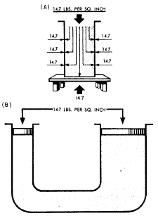
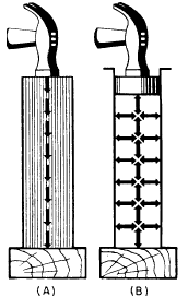
Figure 2-4.—Transmission of force: (A) solid; (B) fluid.
When a force is applied to the end of a column of confined liquid (fig. 2-4, view B), it is transmitted straight through to the other end and also equally and undiminished in every direction throughout the column—forward, backward, and sideways—so that the containing vessel is literally filled with pressure.
An example of this distribution of force is illustrated
in figure 2-5.
The flat hose takes on Figure
2-5. Effects of atmospheric pressure a circular cross section when it is filled with water under
pressure. The outward push of the water is
equal in every direction.
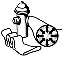
Figure 2-5.—Distribution of force.
So far we have explained the effects of atmospheric pressure on liquids and how external forces are distributed through liquids. Let us now focus our attention on forces generated by the weight of liquids themselves. To do this, we must first discuss density, specific gravity, and Pascal’s Law
The foundation of modern hydraulics was established when Pascal discovered that pressure in a fluid acts equally in all directions. This pressure acts at right angles to the containing surfaces. If some type of pressure gauge, with an exposed face, is placed beneath the surface of a liquid (fig. 2-6) at a specific depth and pointed in different directions, the pressure will read the same. Thus, we can say that pressure in a liquid is independent of direction.
Pressure due to the weight of a liquid, at any level, depends on the depth of the fluid from the surface. If the exposed face of the pressure gauges, figure 2-6, are moved closer to the surface of the liquid, the indicated pressure will be less. When the depth is doubled, the indicated pressure is doubled. Thus the pressure in a liquid is directly proportional to the depth.
The hydraulic jack is perhaps one of the simplest forms of a fluid power system. By moving the handle of a small device, an individual can lift a load weighing several tons. A small initial force exerted on the handle is transmitted by a fluid to a much larger area. To understand this better, study figure 2-19. The small input piston has an area of 5 square inches and is directly connected to a large cylinder with an output piston having an area of 250 square inches. The top of this piston forms a lift platform. If a force of 25 pounds is applied to the input piston, it produces a pressure of 5 psi in the fluid, that is, of course, if a sufficient amount of resistant force is acting against the top of the output piston. Disregarding friction loss, this pressure acting on the 250 square inch area of the output piston will support a resistance force of 1,250 pounds. In other words, this pressure could overcome a force of slightly under 1,250 pounds. An input force of 25 pounds has been transformed into a working force of more than half a ton; however, for this to be true, the distance traveled by the input piston must be 50 times greater than the distance traveled by the output piston. Thus, for every inch that the input piston moves, the output piston will move only one-fiftieth of an i n c h.
This would be ideal if the output piston needed to move only a short distance. However, in most instances, the output piston would have to be capable of moving a greater distance to serve a practical application. The device shown in figure 2-19 is not capable of moving the output piston farther than that shown; therefore, some other means must be used to raise the output piston to a greater height.
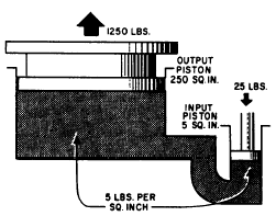
Figure 2-19.—Hydraulic jack.
The output piston can be raised higher and maintained at this height if additional components are installed as shown in figure 2-20. In this illustration the jack is designed so that it can be raised, lowered, or held at a constant height. These results are attained by introducing a number of valves and also a reserve supply of fluid to be used in the system.
The hydraulic brake system used in the automobileis a multiple piston system. A multiple pistonsystem allows forces to be transmitted to two or more pistons in the manner indicated in figure 2-21. Note that the pressure set up by the force applied to the input piston (1) is transmitted undiminished to both output pistons (2 and 3), and that the resultant force on each piston is proportional to its area. The multiplication of forces from the input piston to each output piston is the same as that explained earlier.
The hydraulic brake system from the master cylinders to the wheel cylinders on most automobiles operates in a way similar to the system illustrated in figure 2-22.

Figure 2-21.—Multiple piston system.
When the brake pedal is depressed, the pressure on the brake pedal moves the piston within the master cylinder, forcing the brake fluid from the master cylinder through the tubing and flexible hose to the wheel cylinders. The wheel cylinders contain two opposed output pistons, each of which is attached to a brake shoe fitted inside the brake drum. Each output piston pushes the attached brake shoe against the wall of the brake drum, thus retarding the rotation of the wheel. When pressure on the pedal is released, the springs on the brake shoes return the wheelcylinder pistons to their released positions. This action forces the displaced brake fluid backthrough the flexible hose and tubing to the master cylinder.
The force applied to the brake pedal produces a proportional force on each of the output pistons, which in turn apply the brake shoes frictionally to the turning wheels to retard rotation.
As previously mentioned, the hydraulic brake system on most automobiles operates in a similar way, as shown in figure 2-22. It is beyond the scope of this manual to discuss the various brake systems.
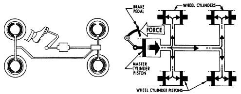
Figure 2-22.—An automobile brake system.