![]() > Productshomepage > Fleet Locator-System
Overview
> Productshomepage > Fleet Locator-System
Overview
(PL
DOWNLOAD
THE SAME DOCUMENT(805
KB) WITH MAPS IN PDF )
RF Fleet tracking Solution
(System
Overview)
Fleet Locator is an integration of three technologies. GIS – Geographical Information system, GPS – Global Positioning system, and Communication technologies VHF/UHF.
On-board unit with GPS
receiver and a data transmission unit based on any of above communication medium
has to be fitted on a Vehicle. This unit sends position and other data to
control station. The data is processed and then a vehicle position is shown on
the map. The stored data can be analyzed to generate various reports.
How it works?
A GPS receiver of the unit fitted on a vehicle takes the lat/long, speed, heading etc. of the vehicle. The communication unit present (RF), transmits the data to Fleet control station. The same data is depicted on a digital map using a GIS server. The data is also stored in a database for future analysis or reference.
Hardware
Mobile
Unit
This unit has to be fitted in a Vehicle to be tracked. Generally it requires a 12V supply, which can be obtained from a vehicle battery. On-board unit comes with various options.
a)
Off-line unit
– This unit has a GPS receiver and a non-volatile memory to store the data.
The data may not be transferred instantly since it does not have wireless
transmission facility. The data can be downloaded from the unit through a serial
connection to the PC and then can be analyzed.
b)
On-line unit
– there are various on-line units available. Essentially it has a GPS receiver
and a wireless transmission unit. Apart from this depending on the requirement a
display unit and voice unit can be attached.
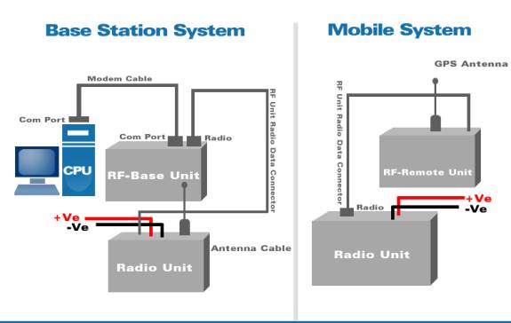
Details of the Hardware
in the Mobile Unit
|
Sr. No |
Hardware Name |
Usage |
|
1 |
RF Remote unit |
For getting location data using GPS and transmitting to base station. |
|
2 |
Radio Set |
For communication |
Control
Station
Details of the Hardware
in the Control Station
|
Sr. No |
Hardware Name |
Usage |
|
1 |
RF base unit |
For communication between Control Station (PC) and RF remote unit. |
|
2 |
Radio Set |
For communication |
Software
GIS
server
This is a control station component, mainly used to depict the position of vehicle on Map. Fleet Locator uses ESRI’s Map Objects to show the vehicles on the map. Map data , depending on the requirement, the features, scale and the area may vary from installation to installation.
The GIS has the following features.
(i) Ability to draw points on a blank white board subject to receipt of Latitude/ Longitude manually (through GARMIN GPS) or via mobile GPS unit in real time.
(ii) Mimic diagram of pre-defined points of site. The mimic diagram (on paper) will be supplied to the party.
(iii) Real time movement of the vehicle on screen. Moving vehicle green, stationary vehicle RED.
(iv) Edit map utility – The ability should be able to add, delete, modify map points in the existing map. Besides, the map utility should be able to create a new point based map. Also, the mobile unit name/ID to be displayed on map.
(v) Replay mode of vehicle movement from stored data.
Communication server
This component is responsible for communication between control station and on-board unit.
The communication medium used is
a) VHF/UHF – Mostly the government organizations like police do have the infrastructure already in use. The same can be used for vehicle tracking.
The communication module should be able to communicate with the mobile units. The mode of communication will be polling from the control station to mobile units. It should have a “PROCESS Monitor Window” for showing real time stations of communication. Other features should include user settable polling interval and baud rate.
To minimize the
battery consumption and extend its life, the following modifications are
proposed in the Communication module software.
·
Selectable polling interval:
30sec\60sec\120\180\240\300sec
·
The Software should be able to
automatically modify the polling rate on either of the following conditions
a)
Velocity of vehicle becomes Zero.
b)
Unavailability of GPS data due to vehicle in shed\indoors.
The polling rate should change gradually from 30 sec to 60 sec to 120 sec to 180 sec to 240 sec to Finally 300 sec on presence of either of the two conditions. When either of the above two conditions vanishes i.e., velocity becomes Non-zero or GPS data is available the polling rate should again reset to the original rate which may be 30 sec or 60 sec.
Database server
This component takes care of non-GIS data. like users, vehicles, position data, messages etc. Currently the solution supports MSSQL Server, Oracle, Interbase and MS Access.
(i) The software is able to identify & analyze the following points.
(a) Trip start point to destination 1 and back
(b) Trip start point to destination 2 and back
(c) Trip start point to destination 3 and back
(d) Trip start point to destination 4 and back
(e) Trip start point to destination 5 and back
In all case, the trip start point remains the same but the destination changes.
(ii) The software should provide station wise analysis. The format should be
|
Sl. No. |
Date/Time |
Station
1 |
Stoppage |
Unit ID |
||
|
From |
To |
In time |
Out time |
001 |
||
|
1 |
12.00 1-4-03 |
12.00 2-4-03 |
9.15 |
9.25 |
10 min |
|
|
|
|
|
14.20 |
14.40 |
20 min |
|
|
|
|
|
21.00 |
22.15 |
1 hr 5 min |
|
More than scheduled stoppage is denoted in RED.
(iii) Trip Time
The trip time should be give the total time and distance covered (approx) from any given point to another point/ same point e. g. the format can be station A-stn B – stn A or stn A- stn B.
(iv) Erase facility of old records to prevent hard disk full phenomena.
Fleet
Locator Functionality
1)
Get Latest Position
Get the latest position of the vehicle and show the vehicle on map
2)
Show Vehicle on Map
Show the vehicles last position on the map
3)
Continuous Monitoring Vehicle
Used to Auto Track vehicle continuously.
4)
Trace Path
Used to trace path of vehicle along with Date, Time Stamp and Speed
5) Reports
a)
Stoppage Report
Used to find stoppages taken by Fleet(s)
b)
Message History
Used to find Sent/Received Messages to/from On
Board Unit and Positions
c)
Trip Report
Used to make trip analysis
(PL
DOWNLOAD
THE SAME DOCUMENT(805
KB) WITH MAPS IN PDF )
![]() > Productshomepage > Fleet Locator-System
Overview
> Productshomepage > Fleet Locator-System
Overview