
(text of article published in "SpareParts",
the magazine of the Constructors Car Club, Wellington, New Zealand http://www.constructorscarclub.org.nz
)
I have been exploring different ways to measure the toe-in and general wheel alignment on a project car. The best way of course is to take it to an alignment specialist, just as the best way to get a car in the first place is to go buy one from the shop.
Having got that out of the way, the following are a number of other options that are available, some of which I have tried.
1.
The tape-measure
This involves simply measuring between the wheel rims with your carpenter’s tape. The main problem is that there is not usually a clear space all the way from one side of the car to the other at wheel centre height. If there is, then this is probably as good as most of the following, except it does need very careful reading of the tape as to be effective, you really have to be able to get repeatable readings that are accurate to half a millimetre. This also depends on the wheel rim being true. You can check this by just repeating the exercise after rolling the car along a bit. See Fig 1.
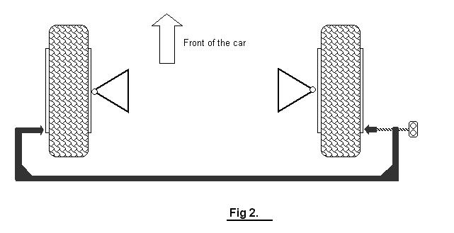
2.
The giant micrometer
I made up this “C” clamp shaped device which could reach round from the outside of one front wheel to the outside of the other. I made it from RHS steel and included a length of threaded rod to adjust the device to exactly the rim-to-rim distance I was checking. The idea was to set this for the rear side of the rims, then move it to the front side so as to be able to observe the amount of toe-in. See Fig 2. This worked OK, but making the device stiff enough for the purpose also made it very heavy, so it was hard to make sure it was taking a measurement without imposing some load on the rim at the same time. It had the advantage over the tape measure that it didn’t need a straight line between the wheels, and it measured toe-in directly with a single measurement. (no maths !!) I was not confident I was getting better than 1 or 2 mm accuracy however.
3.
Stick a pin in your tyre
This is a neat method I found on a Formula Ford site. The attractive thing about it is that it enables you to draw up the whole geometry on the floor of your garage with a piece of chalk. The steps are like this.
I note that this will not give the “true” toe-in measurement. This is because the wheels have not been free to follow their “natural” centre-line as this would result in a track change that the suspension will not permit (I hope). If the car is equally weighted left and right for each axle then the resulting wheel track lines probably represent about half of the real toe-in angle. This method will still work OK if the wheels are not absolutely true, i.e. if they have a bit of wobble in them or the rims are damaged.

4.
The sideways skateboard method
The idea here is to place one front wheel on a platform that is free to slide sideways as the car rolls forward and backward. The amount that the platform moves sideways indicates the degree of toe-in for that pair of wheels. See Fig 4. I used a piece of particle board for the platform ( N.B. this is only a 600kg car), and some one inch pipe for the roller. I found that I had to place strips of metal above and below the roller at each end to make sure that during the exercise the roller only touches the floor and the platform at each end of the platform. If this was not the case then the roller would skew slightly on each movement and I found the readings not to be repeatable. The other side of the platform was supported on a short roller, but a ball of appropriate diameter would actually work best. The important point is to arrange it so the platform is supported cleanly at three points only. This will ensure that forward and backward movement of the vehicle will produce pure sideways movement only of the platform. To obtain a convenient reading, I clamped a pointer onto the roller with vice-grips and drew a scale on a piece of cardboard. Rolling the car back a forward about 250mm, gave 20mm or so movement of the pointer on the scale. This calculated out to be about 2mm toe-in at the rims.
I found I could get very accurate and repeatable readings with this device, and it was very easy to adjust the toe-in to any value required. This is definitely the most accurate backyard method. The main advantage is that it does not depend on the rim being straight, and it can measure more finely than you can do with a ruler or tape measure. But it only gives total toe-in. This is OK for the front axle, but for the rear it does not let you know which wheel is toeing in more than the other-one. 2mm of toe-in might actually be 12mm on one side and 10mm of toe-out on the other side.
Using this device I found actually that I had about 2mm toe-out at the rear of the RoadRat, but I could not tell if one side had more than the other. Reading up on wheel alignment from several sources I came to the conclusion that generally, unless you are having trouble with turn-in, the general rule is always run a bit of toe-in on all axles. So I needed to find a reliable way to make sure I had just a bit of toe-in equally on both rear wheels.

5.
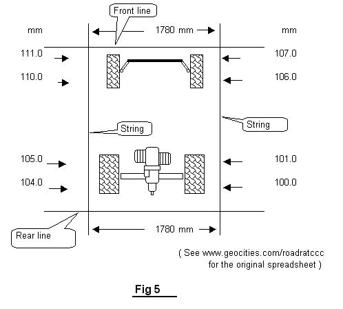
The cat’s cradle
This method involves setting up a string-line at hub level each side of the car. These two strings must be parallel, and set as close as possible to the car. It is a fiddly business getting these strings adjusted just right. Particularly as the front and rear track are rarely the same. The measurements to be taken are pretty obvious, basically the distance from the rim to the string at the front and rear of all four wheels. These measurements have to be taken very carefully, with the ruler dead square to the rim and perfectly horizontal. The best you can probably get is 1mm accuracy and this is probably not really good enough. However, if you move the car half a wheel rotation and repeat the exercise, this will enable more accurate results. See Fig 5.
It occurred to me that even if the
strings are not parallel to the car, the alignment can still be checked by doing
a bit more geometric calculations. So I set a spreadsheet on the computer to
enable this to be done. This does require a few more measurements, like the
wheelbase etc. but it also gives a bit more information as well so you can check
changes in track as you make changes in toe-in. I will put this spreadsheet on
the RoadRat website in case anyone would like to give it a go with their car.
Following is downloadable Excel file for this calculation.Left click the icon to view it, right click it to save and use the file.
. . . . . .
I
found I had slight toe-in on one side at the rear, and about 3mm toe-out on the
other. So I corrected them to slight toe-in both sides.

The RoadRat has a version of the VW “IRS” rear suspension which is difficult to adjust in that there is no single adjustment for just toe-in. So I bungeed a builder’s spirit-level onto each rear wheels while I was making the adjustments to make sure they both wound up with similar chamber angles. The exercise did increase the track by 2 mm and did affect the overall left-right ride height. And I have yet to re-check the diagonal wheel weights.
6.
All four on the floor
How do you know that your car has equal weight on each wheel of each axle? (John Bell will be sniggering at this one. Three wheel cars do have an advantage here.) Maybe the weight is being carried 80% on one diagonal pair and only 20% on the other diagonal pair. This must affect handling, braking, wheel traction and tyre wear. The following is a method I have used to check this out.

7. Call in the professionals
All the tinkering I had done seemed to make the car handle a little bit better. But I kept thinking that there could still me some benefit in getting a professional job done on the car otherwise I would always be wondering if my stubbornness was causing me to miss a vital adjustment that might make a really big difference. So I took the RoadRat in to Autoline where I found club member Brian Hanaray in charge of the electronic alignment wizardry. After a fair while working his magic with blinking lights and computer printouts and such there was good news and bad news.
The good news was that I wasn’t far out. I was certainly within the tolerances of the measuring equipment that I was using (i.e. about half a millimetre) on the front and rear toe in and my camber angles were within 0.2 of a degree. I was pleased about that as it sort of vindicated all the work described above. However, A couple of other problems turned up. I won’t bore the non-VW minded readers with the details but really I need to re-bush the top beam bearings and change some packing washers round so that king-pin inclination and caster can be adjusted to get equal angles on both sides of the car. They are currently a degree or two out, and beyond the range of adjustment possible without pulling things seriously apart. But I am very pleased to have some base data to work with so I now know what I need to do. I note that this necessary information is not so easy to calculate with string and chalk technology… but I might just have a go at working out a way to do it.
RoadRat site >>> www.oocities.org/roadratccc