Build This Low Cost 1/2 H-Bridge
How To Hook Up A Microcontroller To The Interface Chip
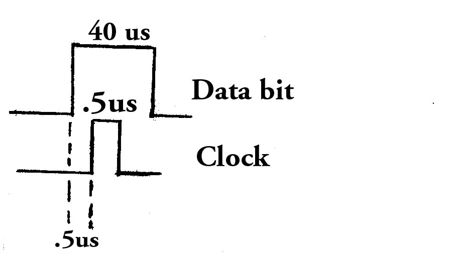
A computer or a microcontroller can be used to communicate
with the Interface Chip over 3 wires. Pin 7 on the Interface Chip is the input for the data bit. When the pin is low it is a zero data bit. When the pin is high it is a one data bit. Your microcontroller must output the data bit before the clock pulse. The data bit must be at least 40 us long.
Pin 33 on the Interface Chip is the input for the clock bit. Your microcontroller must output a high pulse for
at least .5 us.
Pin 5 on the Interface Chip is an output pin. When this pin goes high it is to let your microcontroller know that it is ready to receive the next command. This pin will go low if the Interface Chip is getting a signal from the "VEX" transmitter. This pin will also go low and stay low if there was a communication error between your microcontroller and the motor controller chip.
Pin 4 is an output pin. If there is a communication error between the motor controller chip and your microcontroller, this pin will go high and stay high. A reset must be done in order to clear this error.
List Of The Commands
There are 21 commands that the motor controller chip understands. All the commands are 3 bytes or 24 bits long. The format for the commands are as follows.
The 1st byte that is sent is always the command byte which
is the left most number on the list below.
The 2nd byte sent may be a PWM byte. It is a number between
0 and 50. When a 0 is sent the P.W.M. pulse is low which
means the motor will be off. When the number 50 is sent the
P.W.M. pulse is high which means the motor will be on at
full power. When the number 25 is sent the motor will run
at about half power. As seen on the list sometimes the 2nd
byte is just 0 which is being used just for a place holder.
It has no affect on the motor.
The 3rd byte sent may be a PWM byte or an error checking
number.
For example:
To order motor 1 to go at full speed and motor 2 to go at
half speed forward, the command would be.
1 50 25
To order motor 7 to go backward at 10% power, the command
would be.
16 5 16
1 Motor 1 & 2 forward, PWM #, PWM # (no error checking)
2 Motor 1 & 2 backward, PWM #, PWM # (no error checking)
3 Motor 1 forward, PWM #, 3
4 Motor 1 backward, PWM #, 4
5 Motor 2 forward, PWM #, 5
6 Motor 2 backward, PWM #, 6
7 Motor 3 forward, PWM #, 7
8 Motor 3 backward, PWM #, 8
9 Motor 4 forward, PWM #, 9
10 Motor 4 backward, PWM #, 10
11 Motor 5 forward, PWM #, 11
12 Motor 5 backward, PWM #, 12
13 Motor 6 forward, PWM #, 13
14 Motor 6 backward, PWM #, 14
15 Motor 7 forward, PWM #, 15
16 Motor 7 backward, PWM #, 16
17 Motor 8 forward, PWM #, 17
18 Motor 8 backward, PWM #, 18
19 All motors stop, 0, 19 (pins low)
20 Pin 14 high, 0, 20
21 Pin 14 low, 0, 21
Next Page
Home Page