Building A 52 INCH Robot With Arm
Let's Look Inside The Motor
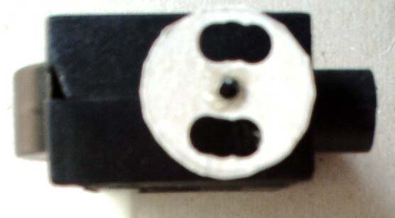
Take the vac apart and pull out the drive motors. By looking at them you can see there is no optical encoder wheel. What an optical encoder wheel does is to break a light beam as the motor turns there by giving X amount of pulses for 1 turn of the wheel. Lets build one for the motor.
The encoder wheel is made from cardboard. Cardboard will be used in many places in this project. Where did I get the cardboard from? Cereal boxes. The shaft of the encoder wheel is a "panel nail" the type of nail that is use to put up wood panels in a house. The length used here is 1 5/8".
I used a compass to trace out a circle on the cardboard that is a little smaller than the width of the body of the motor case. I used a paper hole punch tool to put the holes in the wheel. Use the small hole that is made by the tip of the compass to find the center of the wheel to put the shaft (nail) thru. Put a little glue on the head of the nail to hold on the encoder wheel, let it dry.
The shaft will go into the center hole of the worm gear. First file off a little of the motor case wall so that the shaft does not touch the motor case walls. Put a little glue on the tip of the encoder wheel's shaft (nail) and push it into the center hole of the worm gear. Let dry and put the case back on the motor.
I will not go into details about the electric part of the robot in this tutorial. I will say that we will use the I.R. led and photo transistors found in the vac as the light beam and that we will feed the output to the comparator input on a "PIC" chip.
You will have to make the change to 2 motors. One modified motor will be used in the robot's base and the other in it's arm. This means you will need to buy 2 vacs. and you will have a spare battery and remote as well as other types of motors.


Next Page