Builder’s Notes & Comments
Page 7
Back
to Airframe Log Index | Back
to Home Page
24 Sept. 04
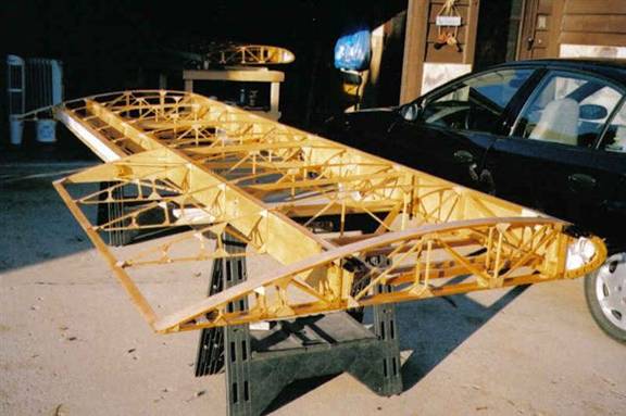
Sanded and varnished
both wings with EV400 epoxy varnish. One coat was put on by brush. Reduced 50%
like the instructions called for on new wood applications, I had the help of my
brother Tim and an old friend that I use to fly Electra’s with, Paul Struss. I
had a little varnish left over so I applied a second coat to the leading edge
nose “D” section and the inboard and outboard ply strips on each wing.
23 May 05
Made a template
for the aileron control arm, copied it to a sheet of 2024-T6 aluminum then cut
out both control arms. Used a 7/8 “hole saw and drilled the hole where the
control arm bushing goes and drilled the 1/8” hole so the bushing can be riveted
in place. Bent the arms down to the 1” measurement shown on the plans son the
control linkage won’t rub on the wing strut.
30 May 05
Measured and
cut the wing tip and wing root plywood support pieces and glued them in place
for the right wing. Added T-Nuts to each ply doublers. 24 in all.
30 May 05
Started to work
on the instrument panel. Cut the basic shape out of 1/4” aircraft plywood.
Arranged the airspeed on the left, the altimeter on the far right. The oil
pressure and dual EGT gauge are located in the inside of the alt. &
airspeed indicator. The Tiny Tack and turn & bank are located on top of
each other in the center of the instrument panel.
01 June 05
Finished
building the instrument panel. Use 8MM plywood and formed the curve for the top
and glued in place.
02 June 05
Sanded the
instrument panel and put a coat of stain on it then put the first coat of
varnish on. Made a viewing window out of lexan and glued to the left wing root,
between the two spars. This is to be able to see how much gas there is in the
gas tank. Looks great.
03 June 05
Sanded the
instrument panel and put the second coat of varnish on. Started to make the
steel inserts that go in the lift struts. This was made per the plans. 1-1/8 chrome
molly that slips inside the 1-1/4 “6061T6 alum. tube that forms the main
struts. I use the gas torch to heat the ends then squeezed the end in a vise
then fit each unit to the appropriate fuselage attach fitting. I have learned
that when you heat and squeeze, the other end does not stay round. This is
proving to be quite a chore to get the piece to fit in the alum. tubing.
08 June 05
Re did the
strut fittings today, I was not happy the way the first attempt looked. They
came out much better the second time around.
Leveled the fuselage and fitted both wings, measured the struts, cut and
marked the strut fittings for the proper placement of the bolts. Sanded the
instrument panel and put the third and final coat of varnish on. Looks pretty
good.

09 June 05
Set the wings
back in place, re checked for the three degree dihedral and worked on the rear
strut fittings. Heated them up with the torch and bent them to the proper angle
so that they would fit in the fuselage fittings and wing strut attach points.
10 June 05
Welded the
strut/fuselage fittings, painted them with enamel paint. Made four aileron
cable guides out of 3/4 “ would, cut a hole with a 1-1/4 “ forstner bit. This
makes a nice tight fit on the rear strut. Also drilled two 3/8” holes and will
use nylon bushings for the guides. They will be glued in place once the proper
spot has been determined.
11 June 05
Borrowed a
dihedral setting tool form Bauken Noack from the EAA and rechecked the
dihedral. The right wing was a little off so I made the final adjustments and
finished the strut placement. Set the rear struts to allow the wing tips to a
level horizontal position. This allows the wing tips to have a 2’ wash out
since there was a 2’ angle built into the wing attach tubes.
17 June 05
Jerry Eales, my
EAA Tech Counselor came over today and did a pre-cover inspection of the wings
in preparation for covering the wings with PolyFiber. He had only one minor
change to the wing which was to fair in the aileron cap strips with 8 MM ply
and sand to the contour of the aileron to allow the poly fiber a smoother
transition and allow better bonding.
Made a paper
pattern for the wing cover gap seal, marked all of the holes on the patterns
where the T-Nuts are, then traced them on to the .016 2024-T3 aluminum and cut
them out. There will be three (3) separate alum. covers that over lap and one
(1) 1/16” piece of lexan that will over lap the two bottom covers which will
allow me to see into the gas tank.
19 June 05
Re made the
fuel tank hold down straps. The old ones were made out of two pieces of 1 “wide
aluminum and rivets together. I changed it to a one piece s.s.steel strap that
has another piece added to it to help spread the load more evenly when
tightened down. Also added felt to the under side to keep from sliding back and
forth.
Also worked on
the aileron pulley guides. Made 4 of them out of s.s.steel banding material and
fit them to the fuselage for a trial fit.
20 June 05
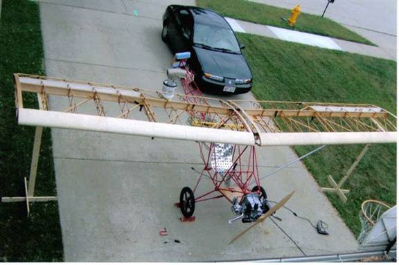
Assembled the
aircraft and leveled it in preparation of building the jury struts. Drilled all
of the holes in the wing gap cover and lined up all of the covers and fit them
all (4) in place. Time consuming process but came out pretty good. I had one
s.s. steel machine screw break off but will be no problem to extract it from
the T-Nut. The cover was not lined up quite right and was binding and finally
snapped the head off of the bolt.
Made four (4)
s.s. steel bands to hold the jury struts in place on the front & rear
struts. Made the left front & rear jury struts and the cross member that
ties the two together. Trial fit and then disassembled the whole aircraft to
put it a way for the night. It is time consuming having to put the wing on to
work on something then have to take it all a part again, but that’s the way it
go’s when you are working out of your garage!!! Also did a preliminary weight
to day and comes out to about 244 Lbs. on an unofficial scale set up. These
numbers are probably off one way or the other. This weight is every thing
except the wing not being covered.
22 June 05
Prepped the
left wing for rib stitching. Put anti-chafe tape on all sharp edges. Applied
two coats of poly-brush to the leading edges of the left wing. Covered both
wing root and tip with 1.6 oz. polyfiber cloth. Covered the bottom of the left
wing and shrunk to a final temp. of 315”. I stopped there because of the light
weight structure. I probably could have gone to 350” but didn’t want to take a
chance on deforming the wing. At the slow speeds of this aircraft. Jerry Eales,
my EAA Tech Rep said this was fine.
23 June 05
Covered the top
of the left wing and shrunk to the same temp. as stated above. Brushed one coat
of Poly-Brush on both the top and bottom of the left wing.
24 June 05
Prepped the
right wing for covering, put anti-chafe tape on all sharp areas. Applied two
coats of poly brush to the leading edge of the right wing. Covered the wing
root and tip with 1.6 oz. poly-fiber cloth. Shrunk to the above stated temp.
Covered the top and bottom of the right wing and shrunk as above. Ironed out
the wrinkles on both wings caused by over applying the poly-tack glue.