CAPACITANCE
![]()
| Every electrical circuit, whether it be a 1 inch length
of wire or a cross-country telegraph line, has three
"built-in" electrical properties: resistance, inductance
and capacitance. The first two of these we have already
encountered in previous chapters: now we are ready to
grapple with the third.
Capacitance is like discarded chewing gum; you may find it almost anywhere. Anytime you have two electrical conductors separated by a nonconducting medium, you have a capacitor; and a capacitor is to capacitance what a doghouse is to a dog; it is where you normally expect to find it. By the light of this definition, you can see that your pocket watch and the furnace in the basement below form a capacitor; so does a wire and the antenna stretched above it; so does a moisture-bearing cloud and the earth beneath. In this free or "stray" state, capacitance is of little or no value; in fact it is often a nuisance. But when it is controlled and "lumped" in definite units, it is every bit as important to electricity as are resistance and inductance. In its "cultured" state, capacitance comes in the packaged form of condensers, the former name for capacitors. There is a wide variety in the form and material used in such capacitors; but before we start studying these practical units, let us see how a simple basic capacitor operates. Once we grasp how it works, we shall know how all capacitance units function. Take a good look at Fig.401. Here we have a capacitor C, consisting of two parallel flat metal plates with an air space between them. Switch S2 connects across these plates. The double-pole switch S1 permits us to connect the battery directly to the plates. An ammeter, an instrument for indicating both the intensity and direction of any electrical current passing through it, is inserted in the lead going to the top plate of the capacitor. To begin, let us say that S1 is open and that we have momentarily closed S2 and then reopened it. Now, suppose we close switch S1, as we do so the ammeter pointer flips over and then drops back to zero, indicating that a momentary current passed through it. Next, let us open S1 so as to disconnect the battery. What happens? nothing; the ammeter pointer does not budge. But suppose we now close S2. as we do so, the ammeter needle flicks again, but in the opposite direction, indicating a reverse flow of energy.
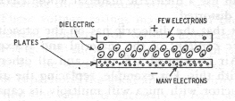
Fig.401 test set-up shows capacitance effects PARADOX OR SENSE? Several questions should be pulsing through your head at this point; Why did current flow in this circuit when we connected the battery? there was no complete circuit, for the plates of the capacitor were separated by insulting air. After the current stated flowing, why did it stop? Where did it the current come from that caused the meter to flick when we closed S2? It could not come from the battery, for that had already been disconnected. The explanations, as usual, go back to electron theory. the momentary closing of the switch S2 before we connected the battery allowed any excess of electrons on either capacitor plate to flow through the switch and balance the electron distribution. at the instant the battery was connected, however, the positive terminal put a strong "come hither" on the negative electrons of the top plate, and they surged through the wire and the ammeter to that terminal, causing the ammeter to register their passage as they did so. At that same instant, the pent-up excess of electrons on the negative terminal of the battery rushed out on to the bottom plate of the capacitor like school kids spilling out onto the playground at recess. The result of this simultaneous "push-pull" action was to leave the top plate with a deficiency of electrons, giving it a strong positive charge, while the lower plate was strictly "Standing Room Only" with electrons and so had a negative charge. As more and more electrons left the top plate and crowded on the lower plate, the charges on the two plates increased in opposite directions until the difference between them was exactly equal to the difference in potential between the two terminals of the battery. at this point, the electrons stopped flowing, because the pushing and pulling forces of the battery terminals. Nothing happened when we opened S1, for there was no path by which the excess of electrons on the lower plate could reach the electron-hungry upper plate. Since this state of unbalance still existed, a voltage equal to that of the battery itself had been disconnected. The instant we closed S2 we provided the needed connecting path, and the displaced electrons rushed through it and through the ammeter to the upper plate. Since this time the electrons were flowing to the upper plate instead of away from it - as they were when the battery was first connected - the ammeter pointer moved in the opposite direction. As soon as the electrons were once more evenly divided between the two plates, they creased to flow; and we were right back to the point we were before we started charging and discharging the capacitor. We might have made one other experiment: When we had the battery connected to the capacitor (S1 closed), if we had slid a sheet of glass between the plates, we should have noticed that the ammeter pointer flicked again, indicating that more charge was moving into the capacitor. When we removed the glass, the pointer would have moved in the opposite direction, showing that this new additional charge had moved back out of the capacitor. An explanation of why the material used as the insulating medium of a capacitor ( it is called the capacitor dielectric) affects the charge the capacitor will take will be given a little later. It is apparent that a capacitor is a device for storing electrical charge. The measure of its ability to do this storing is its capacitance. The amount of the charge stored depends upon how many electrons we can force to leave the top plate and congregate on the bottom plate. We know that the more voltage we have in our charging battery, the more power we have to do this forcing; so it should come to no surprise that the unit used to measure the capacitance depends both on the number of electrons stored and the voltage necessary to do the storing. This unit is called the farad . One farad is the capacitance of a capacitor in which a coulomb (6.28 X 10 to the power of 18 electrons) of electricity is stored when an e.m.f. of 1 volt is applied. This unit is too large for practical use: so the microfarad( uf), a millionth part of a farad, and the micro-microfarad (uuf), a millionth part of a microfarad, are always used in the radio. THE WHY OF CAPACITANCE we have explained what happens when a capacitor is charged, but we have not explained why. Truth to tell, the pundits of electronics tend to take refuge in such phrases as " it is believed", " the theory held"; and "we may assume" when they go to talking about this subject; but here is what is generally thought; A charged capacitor looks like Fig.402 in which the ellipses between the plates represent, in a greatly exaggerated form, the out-of-orbits of the electrons of the dielectric atoms in their paths about their respective positive nuclei. the orbits are out-of-round because of the attraction of the positively charged upper plate and the repulsion of the negatively charged lower plate. Were the electrons of the dielectric free to move; they would go straight to the positive plate; but since they are tightly bound, the best they can do is deviate slightly from their normal circular path
Fig 402 Capacitor plates after being charged. When these orbits are comparatively easy to push out-of -the round, their counter-repelling action on the electrons trying to muscle their way on to the negative plate will be comparatively weak, just as a weak spring puts up a feeble resistance to being compressed; consequently a large number of electrons can force their way into a plate. The capacitance of the capacitor will be larger than it would be with a dielectric material in which the electron orbits were harder to distort. In the latter case, since the dielectric electrons would stubbornly refuse to budge from their orbits, the electrons trying to wedge their way on to the negative plate by distorting these orbits would be rebuffed, and the storage ability would be lessened. We could increase the capacitance by using a thinner slice of dielectric material, allowing the plates to come closer together. This would reduce the total number of the repelling dielectric electrons and so permit more electrons to collect on the negative plate of the capacitor. It is evident, then, that we can increase capacitance in three different ways: (1) We can increase the size of the active portion of the plates. The active portions of the plates are the portions that are directly opposite each other and with the dielectric material squarely between them. Increasing the size of these portions means that we have more electrons to draw from the positive plate and more room on the negative plate to store them. When you remember that the resistance of the electrons of the dielectric material is "softened up" by the double action of the lower and upper plates, working as a combined pushing and pulling team, you can see why only the portions of the plates considered active have much effect on the capacitance. (2) We can reduce the thickness of the dielectric material as discussed above. (3) We can use a dielectric material whose electron orbits are more easily distorted. The effect that the dielectric has on the capacitance is called the dielectric constant of the material and is expressed by the symbol K. Air is assigned a K of 1, and all other materials are compared with this. For example, replacing the our dielectric of given capacitor with mica will multiply its capacitance about 5 to 7 times; so we say that mica has a K of 4.5-7, and some rutile ceramics have a K of several hundred. No wonder the little cusses can pack so much capacitance in so small a space! An ideal capacitor would be one with insulation so perfect that absolutely no current could leak across from one plate to the other; but ideal capacitors are like ideal picnics - they are never quite realized. We have no perfect insulators, and there is always
Fig.403. These capacitors illustrate some of the many types the technician will encounter in serving some leakage. A capacitor with high leakage current is said to have a high power factor; just remember that in capacitors power factors are like living costs - the lower, the better. If we keep increasing the voltage across the plates of a capacitor, we eventually reach a point where the current will break through the dielectric and destroy it (unless, of course, it is air). Increasing the thickness of the dielectric will make this breakdown voltage higher, but it will also reduce the capacitance. Most capacitors used in radio work carry, in addition to their capacitance value, a marking indicating the maximum voltage with which they are to be used. These voltage ratings may vary all the way from a few volts to several thousand for various applications. The picture ( Fig 403.) shows the wide variety of capacitors used in radio work. In the next chapter we will take up the actual construction of capacitors, the good and bad points of each type. We will also find out why it is necessary to have so many different forms of capacitors when they all operate on the same basic principle.
|
|
|
|
|
|
|