|
|
|||
|
HOW CAPACITORS ARE MADE
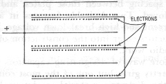
There are more ways of designating capacitors than there are of describing pretty girls, but one of the most common methods is to refer to the dielectric material; so let us begin with air capacitors - those with only air between their plates. The simple capacitor discussed in the previous lesson used only two plates, but most air capacitors use several. The plates are divided into two sets, with all the plates of each set connected together, and with the plates of one set interleaved with the plates of the other, as shown in Fig. 501. This is to economize on space. You will recall that in a charged capacitor the electrons are crowded onto that portion of the negative plate facing the positive plate. That means that in a simple capacitor only one surface of the plate is used for electron storage.
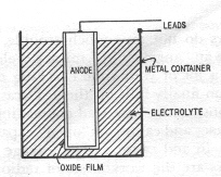
However, as can be seen in Fig.501, when the plates are interleaved, each surface of each negative plate is charged with electrons when it is between two positive plates, and the result is the same as doubling the size of the plates in a two-plate capacitor. It is just like buttering your bread on the same side!!! By arranging our capacitor so that we can control the degree of interleaving of the plates, we can produce a variable capacitor similar to most air-spaced units used in radio work. Very stable as to capacitance, they have almost zero leakage current. They are bulky, though, and it is difficult to build very much capacitance into a reasonable space . You seldom see air capacitors of more than 500 µµf. The main trouble that develops in these capacitors is warping or bending of the plates so that they touch and short out. Occasionally sufficient dust gets between the plates (the rotor) must move, and a sliding wiper contact is used to make an electrical connection to this set. Sometimes dirt or corrosion causes this contact to become erratic. A capacitor of considerably greater capacitance can be built in the same space by using thin sheets of mica as the dielectric and by employing much thinner metal plates. These mica capacitors, as they are called, are enclosed in a case of bakelite or similar material for mechanical protection and to keep out moisture. Since mica has a higher K than air, mica capacitors are more compact than air capacitors. Their leakage is nearly as low; and by using thicker sheets of mica, the breakdown voltage can be made very high. You will find them in ranges from about 100 to several thousand volts, and from 100 µµf to about 0.1 µf. However, they are comparatively expensive; and, as breakdown voltage and capacitance increase, they become quite bulky. A very stable type of mica capacitor, the silver mica, is made by silver plating directly onto the mica sheets instead of metal plates. Mica capacitors do not give much trouble, but they do give some. In fact, like an "angel child," micas develop faults just often enough to waste a lot of your time checking everything else before your suspicion finally falls on them. Occasionally they break down and short out, or the wire lead connecting to a set of plates makes a poor contact and causes an "open" capacitor. More rarely, moisture may get in and cause a high leakage current. Paper capacitors are the workhouse of radio; they really carry the load. Even and a.c.-d.c midget has a dozen or so of them. They usually consist of two long, thin strips of aluminum foil, insulated by paper and rolled up in a tight little cylinder, with wire leads from each strip of foil being brought out of opposite ends. They are covered, treated with oil, and sealed with wax against moisture. Paper capacitors are ordinarily found in values from about .001to several microfarads, and from 100 to 1,600 volts. They are more compact than micas and cheaper, but they somewhat higher leakage currents and deteriorate with age because of the gradual penetration of moisture into the paper. Immersing a paper capacitor in certain types of oil increases its breakdown voltage and also increases its life because the oil prevents the entrance of moisture. That is why military equipment and equipment that must be dependable, uses oil-filled capacitors instead of the ordinary paper kind. The smaller ones are sometimes called "bathtubs." Thin plastic films are also used, in place of the paper, as a dielectric, and some of these plastic-film capacitors have electrical qualities superior even to mica units. Paper capacitors have the same shorting and open troubles to which micas are occasionally prey, but they have them much more often. They are more likely to become leaky, too; and if they become too hot, the wax runs out of them and allows moisture to enter easily. Still they are by far the most often-used capacitors in radio because of the low cost. For securing the most capacitance in the least space for the smallest amount of money, electrolytic capacitors are the answer. These two kinds, wet and dry. Fig. 502 is a sketch of a wet electrolytic. It consists of an aluminum plate, called the anode, immersed in an electrolyte, such as a boric acid solution. The anode has on its surface a vet thin oxide film that has been formed electrochemically prior to assembling the capacitor and putting it into its case.
Following the previous explanations, you might jump to the conclusion that the electrolyte is the dielectric, but that is not true. The dielectric is the thin oxide film - which incidentally has a K of about 10. The aluminum anode forms one plate of the capacitor, and the electrolyte forms the other; the metal container simply serves as a means of making contact with the electrolyte. Dry electrolytic, like dry cell, is somewhat of a misnomer. Damp electrolytic would be better, for in such a capacitor the liquid electrolyte is replaced with a paste. What is more, the anode is replaced with an oxide-coated strip of aluminum foil, and the container is replaced with an uncoated of foil called the cathode foil. These two strips of foil, with the electrolytic paste and a suitable mechanical separator between them, are rolled into a bundle in exactly the same way as are paper capacitors. the result is a convenient cylinder. The capacitance depends on the surface area of the anode and on the nature and thickness of the film. To increase the surface area, the anode foil is frequently etched with acid, and the increased area of the "hills and valleys" thus produced on the foil surface increases the capacitance of an etched-foil capacitor over that of a plain-foil unit by two to seven times. Another way of doing the same thing is to spray molten aluminum on a strip of cotton gauze to produce a grid like anode that will give a capacitance 10 times that of a plain anode strip. these are called fabricated-plate electrolytic capacitors.
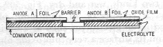
The thickness and nature of the oxide film are determined by the forming process. while a thinner film increases the capacitance, it also lowers the breakdown voltage. Electrolytics used in electronics are found in capacitances of a couple to several thousand microfarads and in voltage range up to 600. By using more than one anode strip or more than one cathode strip, and by having a barrier strips separating these units, it is possible to have more than one capacitor in a single container. Fig. 50 shows one such dual-unit arrangement. Electrolytics are unlike other capacitors in that they ordinarily are polarized. This means that they must be used only with d.c voltages and that the anode must always be connected to the positive point. If these rules are not followed, the oxide film will disintegrate and the capacitor will be destroyed. An electrolytic capacitor is only as good as its oxide film, and various factors can injure this coating. A temporary surge of high voltage may puncture it; but if the voltage is quickly reduced , the film will usually heal itself. A reverse current through the capacitors, impurities in the materials used, long subjection to too high a voltage , and too many months spent lying unused on the shelf will usually result in permanent damage. Electrolytics are usually designed to operate between 32 and 140 degrees F, and they should note subjected to temperatures far beyond these extremes for any great length of time. If the film is broken down, the capacitors usually appears as a partial or complete short, and the leakage current is excessive. If the electrolyte dries out or if one of the connecting leads becomes separated from its foil, the capacitor shows an open circuit. sometimes , before complete evaporation of the electrolyte, the capacitance shows a marked loss of capacitance. Ceramics capacitors enjoy a deserved popularity. They consist of tubes or disks of rutile ceramic with opposite surfaces plated with silver. The two silver coatings are the capacitor plates, and the ceramic material is the dielectric - with a K up into the hundreds. Ceramics, like some women, seem to have everything - small size, high capacitance, high voltage rating, and low power factor. What is more, by regulating the mixture of the ceramic material, the capacitor can be made to have a positive, zero, or negative temperature coefficient, which is another way of saying that the capacitance can be made to increase, stay the same, or decrease with a rise temperature. This feature compensates for heat changes in other components of an electrical circuit. When the capacitance of these components "zigs" with an increase in temperature, you can employ a ceramic capacitor that "zags" an equal amount, and vice-versa, and thus maintain the over-all capacitance constant. The manufacturers did not develop all these different types just to show what they could do. Each types fills a particular need. The choice for a particular job depends upon which will do the work best for least cost. In some spots the most important thing is lots of capacitance; so an electrolytic is used. At another point the capacitor must not change its value; so a silver-mica unit is employed. If the leakage must be extremely low, an ordinary mica serves nicely; and for run-of-the-mill applications, paper capacitors do the job. Where space is at a premium or leads must be kept short, as in high-frequency applications, disc ceramics are the ticket. Air-spaced units are used for variable and semi variable duty because of obvious mechanical advantages. |