OHM'S LAW AND THE RESISTOR
![]()
| We have already learned that an electric
current is made up of a movement of minute negative particles called
electrons; that these electrons are always attracted by a positive
charge, so that an electric always flows from negative to positive; and
that we measure current in ohms.
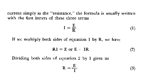
Ohm's law ties the units of currant, voltage, and resistance together, in a simple formula so that if you know any two of them, you can always find the third. the importance of the formulas equalled only by its simplicity and ease of application. Ohms law states that the current, measured in amperes, flowing in any portion of an electrical circuit is equal to the applied electromotive force in volts divided by the resistance in ohms.
Since the current is referred to as the "intensity, " the voltage as the "electromotive force, " and the resistance to the passage of current as the "resistance, " the formula is usually written with the first letters of these terms.
These various forms of Ohm's law enable us to determine quickly an unknown voltage =, current, or resistance if we know the other two. Let us take the circuit of Fig. 201 as an example. Here we have three resistors, of 1, 2, and 3 ohms, respectively, hooked in series across a 12-volt battery. When resistors are connected in series, the total resistance is equal to the sum of their individual resistances; so we know that the resistance from A to D is equal to 6 ohms. We also know that the battery voltage that appears across these points is 12 volts; so we simply substitute
Fig.201 these values in equation 1, and we find the 2 amperes of current will be flowing from point A to point D. USING OHM'S LAW Ohm's law applies to any portion of a circuit. Let's consider just that portion between points A and B. We know that 2 amperes of current are flowing through this, as well as every other part of the circuit, and we know that the resistance between these two points is 1 ohm. Substituting these two values in equation 2, we find that the voltage drop from point A to point B is 2 volts. In the same way we learn that the voltage from B to C is 4 volts, and that from C to D is 6 volts. When these three voltages are added together, they total the same 12 volts with which we started; we have that pleasant and slightly surprised feeling we get when our check stubs and the bank's report on our balance come out exactly together. This pleasant discovery is expressed by Kirchholf's law, another of the rules by which radio and electricity work. Kirchholf's law is a very simple one and it is valuable because it provides a way of checking the accuracy of calculations. The voltage drops in all parts of a circuit, it says, should, when added together, equal the voltage of the source. If, for instance, we had in addition to the 2-, 4-, and 6-volt drops of Fig. 201, an extra 2-volt drop, the total would be 14 volts. The battery (source) supplies only 12 volts so we would know something had gone wrong with our arithmetic and we should try it again. Just to prove how well we can handle Mr Ohm's handy little gadget, suppose we wanted to reduce the current flowing in our circuit from 2 amperes to 1 ampere. How would we go about it? Well, we have battery voltage of 12, and we know that we want 1 ampere of current to flow; so suppose we substitute these two values in equation 3. We come up with 12 ohms as the required resistance. But there are already 6 ohms in the circuit; so we simply put another 6-ohm resistor in series with those we already have - say between points D and E - and our current is reduced to the required 1 ampere. For practice, why don't you figure out the difference that this will make in the voltages appearing at points B, C, and D? In dealing with Ohm's law, there is one thing to keep clearly in mind: it works only when the quantities are expressed in volts, ohms, and amperes. Ten milliamperes should be written: .010 ampere: Two megohms would be expressed as 2,000,000 ohms. FIXED AND VARIABLE RESISTORS Resistance is packaged in units called resistors. some idea of their wide variety of sizes, shapes, and materials can be seen in Fig. 202. The most common type in radio work is the so-called carbon resistor, made by combining powered carbon or graphite with a synthetic resin and an inert material such as talc, moulding this into short sticks and attaching flexible wire leads to the ends. By regulating the amount of carbon or graphite, the resistors can be made to have values from a fraction of an ohm to several million ohms. Cheap and small, they are not capable of handling much current without being damaged by the heating effect of that current; furthermore, they are quite likely to change value with age and temperature. Wire-wound resistors are made by winding a wire made of a high-resistance metal such as Nichrome on an insulating form. Capable of handling much more current than composition resistors, they are also more stable. At the same time, they are more costly and bulky, and occasionally the wire fractures, resulting in their changing without warning from their normal value to an almost infinite resistance. Wire-wound resistors seldom exceed 100,000 ohms in value. It is often desirable to be able to vary the value of a resistor. a slider can be arranged to move along the resistor and to make contact with the resistance element, varying the amount of resistance that appears between the slider can be attached to a shaft passing through the centre of the circular resistance element, and than the variation in resistance can be accomplished by rotating this shaft with a knob. Such a knob-adjusting resistor is variously known as a rheostat, potentiometer, or volume control. the resistance element may be either wire-wound or composition. In volume controls, where the current requirements are ordinarily very small, it is usually composition. WHY RESISTANCE IS IMPORTANT At first glance, you might think that resistance was a kind of villain of the piece. Here we have gone to a lot of trouble trying to cause an electric current to flow, either by building a battery or constructing a generator, and now Old Man Resistance is in there doing his level best to gum up the works by throttling the flow of current! Actually, the ohm is as important as the volt, for, although the volt may be considered the generating force, the ohm is the controlling unit; and if we are to use an electric current, we must be able to control it. Being able to vary the amount of resistance in a circuit gives us a "valve-action" control of the current flowing through the circuit. at the same time, reference to Fig. 201 will reveal another use for resistance, that of "voltage dividing." As can be seen, the 12 battery volts can be sliced up like a length of bologna into any number of smaller voltages by the use of resistors. Still another use for resistance is to enable us to convert a change in current into a change in voltage. Take a look at
Fig.202 Fig. 203. Here we have a variable R1 and a fixed resistor R2 hooked in series across a battery. the amount of current flowing through this circuit will depend upon the voltage of the battery and the resistance of R2 plus that portion of R1 through which the current passes. Any change in the amount of R1's resistance used in the circuit results in a change in the amount of current flowing. We know that the voltage appearing across R2 depends upon the current flowing through it - for didn't Mr Ohm decree that E = IR? So the change in current caused by
varying R1 is faithfully reflected as a change in the voltage across R2. When we start studying vacuum-tube circuits, you will see how important this use of resistors is. HEAT AND POWER In Chapter 1 we defined a good conductor as any material that gave up electrons easily and so permitted a current to flow through it readily. The materials of which resistors are made are no such pushover for an electromotive force, because they do not give up their electrons without a heated struggle. I use the word "heated" advisedly, for actual heat arises from the energy used in prying loose the electrons from the atoms of the resistance material.. Since the electrical force that performs this prying is measured in volts, and since it takes more energy to move several electrons than it does only one, it is not surprising to find that amount of heat produced is related both to the voltage and the current. The amount of electrical energy or power expended - or dissipated as heat, in the case of a resistor - is measured in watts. The power in watts consumed in any circuit is equal to the product of the volts and the amperes; or, expressed in formula form P = EI (4) Equation 2 told us that E = IR; and when we substituted this value of E in equation 4, we have P = I2R (5) Because electrical energy that is transformed into heat is considered lost, we often hear the heat losses of a resistor or conductor called the "I2R losses." Resistors are rated in wattage as well as resistance, and the wattage ratings vary all the way from a fraction of a watt carbon resistors to wire-wound resistors of 100 or more watts. Suppose we need a 1,000-ohm resistor that must pass 50 milliamperes of current. According to equation 5 the wattage requirements will equal to .0502 x 1,000, or 2.5 watts. It is a good practice to allow for a 100% overload; so we select a 5-watt resistor. You have heard about the boast of the packing houses that they use every part of the hog except his squeal. well, the electrical engineers are just as good , for they even put these I2R losses to work. In a vacuum tube, for example, it is necessary to raise the temperature of one of the elements in order to persuade it to give up electrons more easily. This heating is accomplished by passing an electrical current through a resistance wire (the filament) inside the tube. When you look at the incandescent filament of a dial lamp, you are staring some I2R losses right in the face.
|
|
|
|
|
|
|
![]()