![]()
COMPRESSION
Project Report
Spring 2001
![]()
COMPRESSION
Project Report
Spring 2001
This goal of this project was find out whether it is possible to restore
a geometric model after removing most of its vertices, and leaving some
control vertices fixed in their original position. To do that we
randomly pick a vertex and if it is not fixed, we replace its position
with the average of its neighbors. Below I will try to demonstrate the
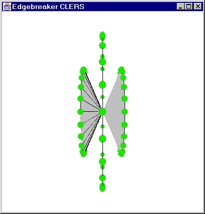
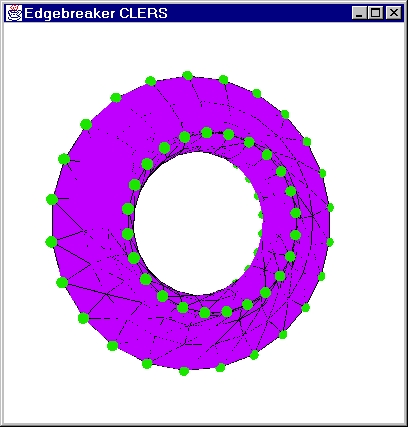
results on the torus model. This model has 288 vertices and 576 triangles.
Torus example 1:
For this example I fixed 1/5 vertices in random order. The non-fixed
points are reset to zero
and the fixed points remain intact.
original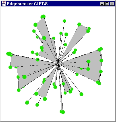
|
2000 lifts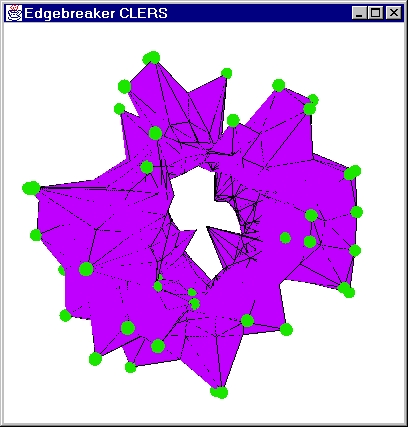
|
4000 lifts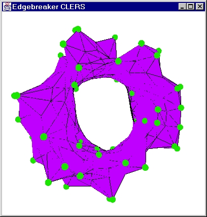
|
10000 lifts -- stabilized model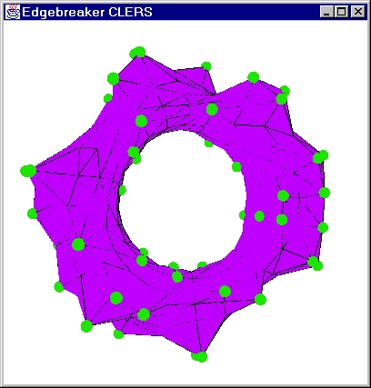
|
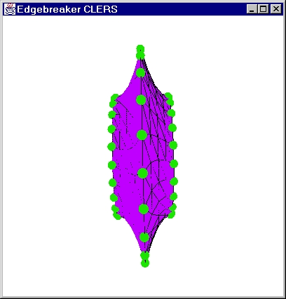
Torus Example 2:
In this example 1/4 points are fixed in non-random order (every 4-th
vertex in the model is fixed). The non-fixed coordinates are set to zero.
Neighbors of the fixed vertices are not touched.
Original side view:
 |
Original front view:
 |
After 1000 lifts
 |
After 2000 lifts:
 |
After 6000 lifts:
 |
Side view of model after 6000 lifts
 |
We also tried to explore the effect of lifting the neighbors of the fixed vertex by the amount equal to the difference between the position of the averaged neighbors and the actual position of the vertex. As a result we get a "sticking out" effect that should compensate for the lack of vertices. We color the surrounding triangles of the fixed vertex in yellow, if the neighbors were moved, and color the neighbors of the moved non-fixed vertices in violet. Below are the results.
Torus example 3:
In this example I fixed 1/4 points in a random order, lifted neighbors
of fixed vertices, and reset non-fixed vertices to zero.
original model side view:
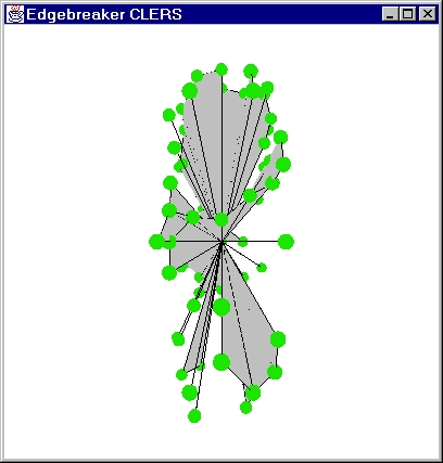 |
original model front view:
 |
Model after 1000 lifts:
 |
Model after 2000 lifts:
 |
Model after 7000 lifts:
 |
Side view of the model after 7000 lifts:
 |
The fact that the model is not fine, i.e. has too few vertices causes
the problem: because the distance between neighbors is big, the lifting
factor for the neighbors of the fixed vertex is big, and as a result we
get sharp peaks sticking out of the model. Nevertheless, lifting
adds more volume to the model, and in the end it looks smoother than the
equivalent model without lifting (please compare pictures of examples 1
and 3). The resulting image from example three looks much closer
to the real torus than the resulting stabilized image in example 1.
Unfortunately due to the "sticking" effect, caused by the large distances
between vertices, the model in example 3 never stabilizes, i.e. it keeps
growing and shrinking the sharp peaks back and forth forever, even though
the vertices that do not have fixed neighbors stabilize and do not move
much.
One of the possible fixes to this problem would be applying a smoothing
function after blowing up the compressed model to increase its semblance
with the original. Using a finer model will also reduce the "sticking"
effect.
Please NOTE: Here I reused some of the code written
by Volker Coors
Source code:
Compression.java
Display.java
NewTriLoader.java
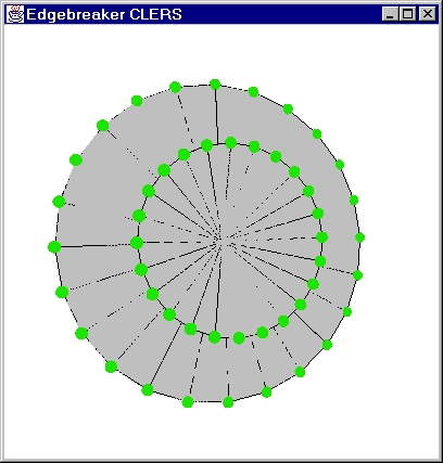
After trying the algorithm on the 3D model we decided to se how the non-closed surface will behave. Here we fix the boundary of the surface and reset all of its interior vertices to zero. Delaunay triangulation is used to generate surfaces and after the boundary is identified all of the interior vertices loose their coordinate information to be redistributed. Each vertex is moved using the average positions of its neighbors. Please see examples below.
2D examples
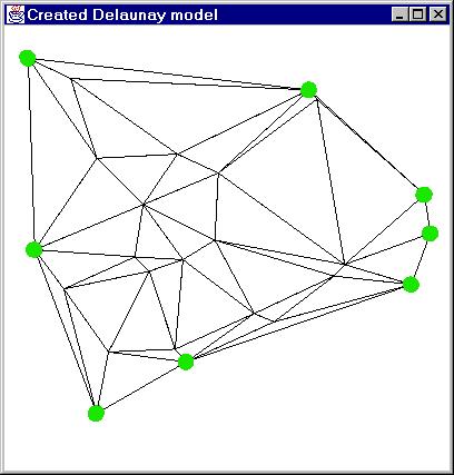
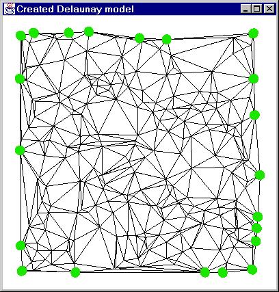
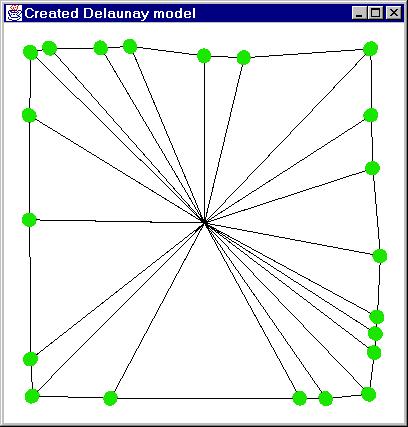
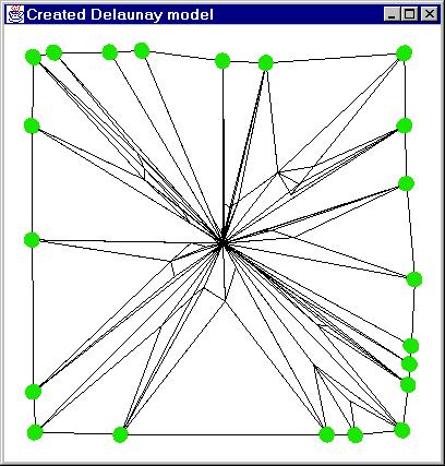
Example 4
25 vertices in the model
Original Delaunay Model:
 |
After removal of inner vertices:
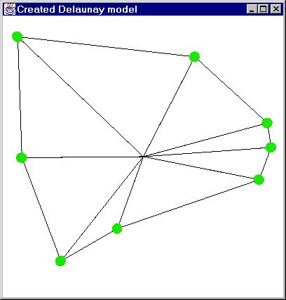 |
After 10 lifts:
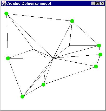 |
After 30 lifts:
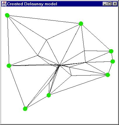 |
After 40 lifts:
 |
After 60 lifts:
 |
After 80 lifts:
 |
Final stable version:
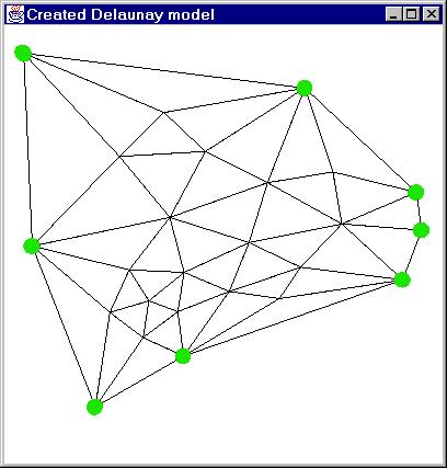 |
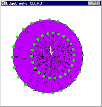
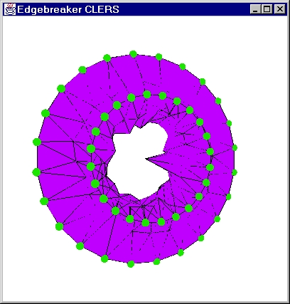
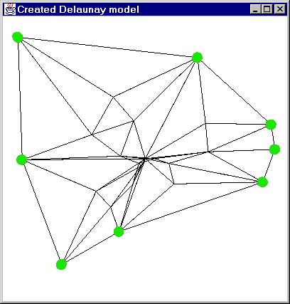
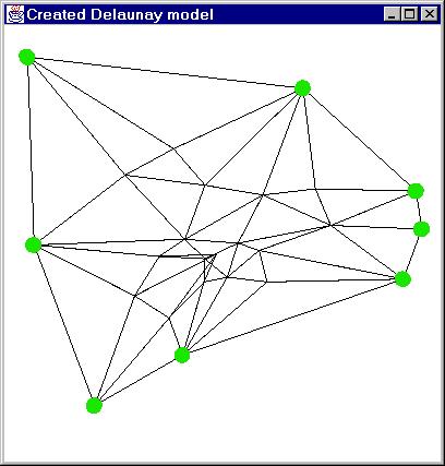
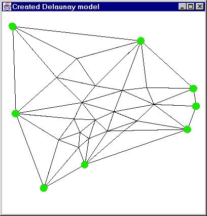
Example 5:
250 vertices in the model.
Original Delaunay Model:
 |
Compressed Model:
 |
300 stretches:
 |
700 stretches:
 |
1400 stretches:
 |
2600 stretches
 |
~5500 stretches
 |
Stabilized version:
 |
As you can see, algorithm generates a more uniform model than the original delaunay model. It is not completely regular, because each vertex has a different degree (different number of neighbors). In the case when every vertex has a same degree we would expect the distance between vertices to more uniform. Also, because the boundary is not uniformly spread, it effects the distances between vertices that are close to the boundary, producing larger triangles closer to the boundary.
Now let us look at the behavior of this algorithm for the surface in
3D.
Example 6
This model again has 250 vertices
Front view of original delaunay:
 |
Side (depth) view of original delaunay:
 |
Compressed model view (side):
 |
Model after 300 stretches:
 |
Model after 1700 stretches:
 |
Several thousand stretches later:
 |
Stabilized model side view:
 |
A view from another side:
 |
Another view:
 |
Bottom view:
 |
As you can see from this example we moved from completely white noise
in the 3D dimension into a smooth surface. This behavior matches
the predictions -- the surface is optimised between the control points.
In a case when we need to build a shape of some particular shape it is
expencive to compute it with other know techniques like bezier curves.
Instead, by carefully selecting control points we can reconstruct the shape
using our simple algorithm.
Source code:
Note: Here I also reused some of the Volker's code. For this
project I merged several of my previously written programs, so the name
of the file "Geomorph" no longer agrees with its content. Nevertheless,
it's the main driver of the project. To compile the program type:
javac Geomorph.java at the command prompt. You may run the program
by typing the following command: java Geomorph. Also, please note
that Display file here differs from the one above.
Delaunay.java
Display.java
Geomorph.java
LineSegment.java