CSC621 presentation (Section 6.7.3 -- 6.7.4)
by Sheng Wen, Oct 23, 2000.
This paper covers the development of an algebraic circuit for the discrete Fourier transform, one of the non-Boolean problems (non-logic circuits). The quality of the circuit is measured by circuit size, the number of circuit operations, and circuit depth, the length of the longest path between input and output vertices. Circuit size is a measure of the work necessary to execute the corresponding straight-line program. Circuit depth is a measure of the minimal time needed for a problem on a parallel machine.
Since the Fourier transform is a widely used technique with important applications in physics, signal processing and computer science, I'll use an example to introduce the general concept.
What is a Fourier Transform? This question is best answered with the aid of an example. A Fourier transform is a representation of some function in terms of a set of sine-waves. The set of sine-waves of different frequencies is orthogonal, and it can be shown that any continuous function can be represented by summing enough sine-waves of the appropriate frequency, amplitude and phase.
Let us consider an imaginary sequence of audio signal as a function of time. The total length of sampling is T. It looks like this:

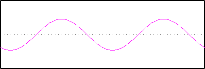
Now we will try and represent this function in terms of sine waves. The first sine wave has a frequency of 2, that is there are two repeats of the wave across T:
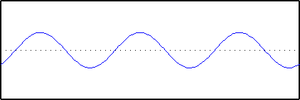
The second sine wave has a frequency of 3; three repeats of the wave across T. It has a different phase, in other words we start at a different place on the wave. The amplitude is also different:
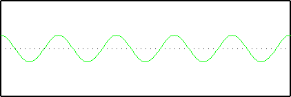
Finally, we introduce a sine wave with a frequency of 5:
Now we add them all together:
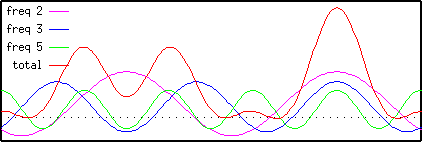
Note that the sum of the three sine-waves is a good approximation to the original signal. Thus we can see that the signal can be represented quite well using only three sine-waves, given the correct choice of frequency, amplitude and phase.
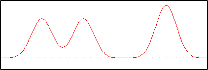
Now we will look at the Fourier Transform of the same signal. Note that the result consists of a series of peaks, the largest of which are at 2, 3 and 5 on the x-axis. These correspond exactly to the sine-wave frequencies which we used to reconstruct the signal. If you look carefully you will also see that the heights of the peaks correspond to the amplitudes of the three waves:
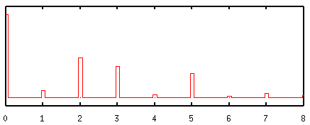
The smaller peaks in the Fourier transform correspond to additional smaller waves which would have to be added to get a perfect fit to the original sequence. Thus we can see that the Fourier Transform tells us what mixture of sine-waves is required to make up any function.
It is often useful to think of functions and their transforms as occupying two domains. They are also referred to as the function and transform domains, but in most physics applications they are called the time and frequency domains respectively as in the example shown above. Operations performed in one domain have corresponding operations in the other. For example, as shown in our text section 6.7, the convolution operation in the time domain becomes a multiplication operation in the frequency domain. The reverse is also true. Such theorems allow one to move between domains so that operations can be performed where they are easiest or most advantageous.
Now let's go back to the development of an algebraic circuit for the discrete Fourier transform. Before getting into the details, let's review some basic concepts and definitions.
Many important functions are naturally computed with straight-line programs (SLP), programs without loops or branches. Such computations are conveniently described with circuits, directed acyclic graphs of straight-line programs. Circuit vertices are associated with program steps, whereas edges identify dependencies between steps. Circuits are characterized by their size, the number of vertices, and their depth, the length (in edges) of their longest path. Circuits in which the operations are Boolean are called logic circuits, those using algebraic operations are called algebraic circuits, and those using comparison operators are called comparator circuits. This talk only examines the algebraic circuit, using the discrete Fourier Transform as an example.
A ring is an algebraic system that consists of a set and two operations called addition and multiplication that obey a small set of rules.
A Commutative ring R=(R, +, *, 0, 1) has a principle nth root of unity w if w Î R satisfies the following conditions:
and
for j = 1, 2, ..., n.
An example of commutative ring is the function: e2p i/n . The sine part of it is what we mentioned above in the section of Fourier Transform example.
The n-point discrete Fourier transform Fn: Rn |® Rn maps n-tuples a = (a0, a1 ,.., a n-1) over R to n-tuples f = (f0, f1,.., fn-1) over R; that is, Fn(a)=f . (An example of this mapping is the two domains: time domain and frequency domain mentioned earlier in this presentation.) The components of f are defined as the values of the following polynomial p(x) at the nth roots of unity:
p(x)=a0+ a1x+ a2x2+...+ an xn-1 (6.21)
the fr , the rth component of Fn (a), is defined as
fr = p(w r) = å akw rk (k from 0 to n-1).
This computation is equivalent to the following matrix-vector multiplication:
Fn(a) = [w ij]´ a
where [w ij] is the n´ n Vandermonde matrix whose i, j entry is w ij, i,j = 0,1,...,n-1, and a is treated as a column vector.
The n-point inverse discrete Fourier transform Fn-1: Rn |® Rn is defined as the values of the following polynomial q(x) at the inverse nth roots of unity:
q(x) =1/n (f0+ f1x+ f2 x2 +..+ fn-1n-1)
That is, the inverse DFT maps an n-tuple f to an n-tuple g, namely, Fn-1 (f)=g, where gs is defined as follows:
gs=q(w -s) = 1/n å f lw -ls (over l from 0 to n-1)
This computation is equivalent to the following matrix-vector multiplication:
Fn-1( f ) = [1/n w -ij] ´ f
Because of the following lemma it is legitimate to call Fn-1 the inverse of Fn.
LEMMA 6.7.3 For all a Î Rn, a = Fn-1 (Fn(a)).
Let f = Fn(a) and g = Fn-1(f). We can prove that gs = as, by changing the order of summation and using the definition of nth roots of unity. (See text p265).
It's obvious that the computation of the n-point DFT and its inverse using the naive algorithms (matrix-vector multiplication) require O(n2) steps. the next we show that a fast DFT algorithm exists for which only O(n log n) steps suffice.
The fast Fourier transform algorithm is a consequence of the following observation: when n is even, the polynomial p(x) in equation (6.21) can be decomposed as
p(x)= a0+ a1x+ a2x2+...+ an-1 xn-1
Here pe(y) and po(y) are polynomials of degree (n/2) -1 .
Let n be a power of 2, that is, n=2d. As stated above, the n-point DFT of a is obtained by evaluating p(x) at the nth roots of unity. Because of the decomposition of p(x), it suffices to evaluate pe(y) and po(y) at y=(w 0)2, (w 1)2,..., (w n-1)2 = (w 2)0, (w 2)1,..., (w 2)n-1 and combine their values with one multiplication and one addition for each of the n roots of unity. However, because w 2 is a (n/2)th principal root of unity, (w 2)(n/2)+r = (w 2)r and the n powers of w 2 collapse to n/2 distinct powers of w 2, namely, the (n/2)th roots of unity. Thus, p(x) at the nth roots of unity can be evaluated by evaluating pe(y) and po(y) at the (n/2)th roots of unity and combining their values with one addition and multiplication for each of the nth roots of unity. In other words, the n-point DFT of a can be done by performing the (n/2) -point DFT of its even and odd subsepuences and combining the results with O(n) additional steps. This is the fast Fourier transform (FFT) algorithm.
We denote by F(d) the directed acyclic graph associated with the straight-line program resulting from this realization of the FFT on n= 2d inputs. First let's look at an example of four inputs to review the straight-line program (SLP). Here the function f+,a (a,b)=a+ba where a is a power of a constant w that is a principle nth root of unity of a commutative ring R. The arguments a and b are variables with values in R.
(1 READ a0) (7 f+,w 0 3 4)
Here, each SLP step is an input, computation, or output step. The notation (s READ x) indicates that the sth step is an input step on which the value x is read. The notation (s OUPUT i) indicates that the result of the ith step is to be provided as output. Finally, the notation (s OP i ... k) indicates that the sth step computes the value of the operator OP on the results generated at steps i, ..., k. We require that s i,...,k so that the result produced at step s depends only on the results produced at earlier steps.
The graph of the above SLP is the familiar FFT butterfly graph shown in Fig 6.1.(p238, text). Assignment statements are associated with vertices of in-degree zero and operator statements are associated with other vertices. We attach the name of the operator or variable associated with each step to the corresponding vertex in the graph. We often suppress the unique indices of vertices, although they are retained in Fig.6.1.
Let function gs is associated with the sth step. From above example, g11 = f+,w 2 (g5, g7)= g5+g7w 2, where g5=f+,w 0 (g1,g2)= a0+a2w 0 = a0+a2 and g7=f+,w 0 (g3,g4) = a1+a3w 0 = a1+a3. Thus,
g11=a0 + a1 w 2 + a2+ a3 w 2
which is the value of the polynomial p(x) at x=w 2 when w 4 =1:
p(x) = a0+ a1 x1 + a2 x2+ a3 x3
Directly from the graph, the size of this circuit is the number of operator statement it contains, 8, in this case, and the depth is the length of number of edges on the longest path from an input to an output vertex, which is 2 in this case. Considering each operator actually contains one addition and one multiplication, the size of this FFT circuit should be 13, and depth should be 4.
A circuit for the 16-point FFT algorithm inputs, F(4), is shown in Fig. 6.7. It is computed from the eight-point FFT on the even and odd components of a, as shown in the boxed regions. These components are permuted because each of these smaller FFTs is computed recursively in turn. (The index of the ith input vertex from the left is obtained by writing the integer i as a binary number, reversing the bits, and converting the resulting binary number to an integer. This is called the bit-reverse permutation of the binary representation of the integer. For example, the third input from the left has index 3, which is (011) in binary. Reversed, the binary number is (110), which represents 12. ) Inputs are associated with the open vertices at the bottom of the graph. Each vertex except for input vertices is associated with an addition and a multiplication. For example, the white vertex at the top of the graph computes f8= pe( (w 8)2 )+ w 8 po( (w 8)2 ), where (w 8)2 = w 16 = w .
Let C(F(d)) and D(F(d)) be the size and depth of circuits for the 2d-point FFT algorithm for integer d=1. The construction given above leads to the following recurrences for these two measures:
C(F(d)) <= 2C(F(d-1)) + 2d+1
D(F(d)) <= D(F(d-1)) + 2
Also, examination of the base case of n=2 demonstrates that C(F(1)) = 3 and D(F(1))=2, from which we have the following theorem.
THEOREM 6.7.1 Let n = 2d. The circuit for the n-point FFT algorithm over a commutative ring R has the following circuit size and depth bounds:
C(F(d)) <= 2n log n
D(F(d)) <= 2logn
This theorem can be proved by induction.