
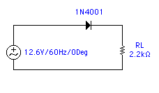
 On the
left is the schematic for a half-wave rectifier circuit. This is the most
simple of the rectifier circuits. Also, the least efficient. With this
circuit you can only recover 180 degrees of the the full cycle. As you
can see, the anode is pointing toward the voltage source. This will result
in a positive pulsating DC voltage.
On the
left is the schematic for a half-wave rectifier circuit. This is the most
simple of the rectifier circuits. Also, the least efficient. With this
circuit you can only recover 180 degrees of the the full cycle. As you
can see, the anode is pointing toward the voltage source. This will result
in a positive pulsating DC voltage. 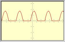 At the right is an example of this. It's really quite a simple concept
when you think of it! If you recall the sine wave on the previous page,
this looks the same, except the negative alternations are missing. This
is easily explained. Imagine that you could stop time every alternation.
We'll start with the positive. As the positive alternation approaches the
diodes anode, the anode becomes more positive than the cathode, causing
the diode to be forward biased. As this alternation goes through the diode,
the measurement line goes up! You can see this in the image.
At the right is an example of this. It's really quite a simple concept
when you think of it! If you recall the sine wave on the previous page,
this looks the same, except the negative alternations are missing. This
is easily explained. Imagine that you could stop time every alternation.
We'll start with the positive. As the positive alternation approaches the
diodes anode, the anode becomes more positive than the cathode, causing
the diode to be forward biased. As this alternation goes through the diode,
the measurement line goes up! You can see this in the image.
Now as time permits the second alternation to go
by, we'll see a change. This is the negative alternation. Now, as the negative
alternation approaches the diode's anode, it causes the anode to be more
negative than the cathode, thus reverse biasing the diode. When the diode
is reverse biased, it blocks the current. You can see this as the straight
lines between positive alternations. This is the basic idea of the half-wave
rectifier! See how easy it is! Now, I'm sure you're thinking that this
seems like a waste, after all, we are wasting half of the cycle! Never
fear! The answer lies on the next page!