|
How To Add Line 23 Widescreen Switching (WSS) to Sky+ What is Line 23 WSS? Widescreen switching automatically controls the aspect ratio of your widescreen
TV when an anamorphic 16:9 picture is being displayed. All Sky Digital
Satellite Receivers output a signal on SCART pin 8 to control the TV's
aspect ratio: This is fine if you connect your Sky box to your TV via SCART, however there are various reasons why this may not be the case:
Because RF, Composite and S-Video connectors do not have a dedicated pin to indicate a WS signal, they use a standard called PAL WSS instead. This involves encoding a special digital signal onto line 23 of the video signal, in much the same way as analogue Teletext. You can find exact details of the format of line 23 in this Intersil Application Note. The good news is that your Sky+ box contains a video chip which is capable of automatically generating this signal and inserting it into all of the above video outputs from your Sky+ box. The bad news is that Sky haven't got round to programming their software to instruct the chip correctly! Unfortunately this means no WSS output on line 23 with Sky+. Update: As of EPG 5 Sky have finally got round to programming the line-23 output on the Sky+ boxes themselves! This also means that CGMS-A is now being placed on line-23 for shows that require it. Another added advantage to this software upgrade (and one that my mod provided too) is that WSS now works correctly on TVs connected via a magic eye and RF2. Well done Sky - Only about 6 years late, but better late than never! Sadly I have now removed my much loved, but now somewhat redundant, line-23 mod from my Sky+ box. It has served me failthfully without a glitch since I built it, but is sadly now surplus to requirements. :( What Have Sky Said About Line 23 WSS? Sky do not seem to be interested in implementing line 23. Here is what they had to say to digitalspy back in February 2002:
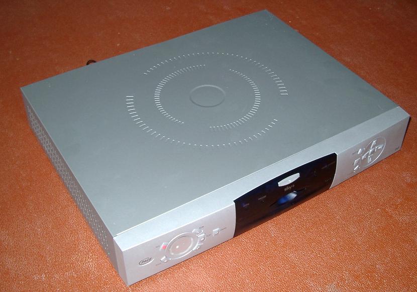
And here again in March 2003: But finally in late 2008 we began to see a minor enhancement in EPG5 deliver line-23 to all Sky+ boxes. Presumably a similar modification might just follow for the standard Sky boxes if they are capable of it. .Can I Add Line 23 WSS to my Sky+ Box? If you have a Version 1 Pace Sky+ box, then the simple answer is yes! You will need the skills and tools to construct a simple circuit on strip-board and program a PIC micro-controller from your PC. You will also need the nerve to open up your Sky+ box and fit the modification. In doing so you will void any remaining warranty and also risk damaging your box, possibly beyond repair. While I have successfully performed this modification on my own Sky+ box, I will accept no responsibility for any damage you cause to yours, either as a result of errors in these instructions or your inability to follow them. Unfortunately, at this time, no known mod is available for Version 2 Sky+ boxes from either Pace or Amstrad. This is because these boxes use a different chip set and do not have the Conexant Video DAC. If I find or hear of a solution for Version 2 boxes (please don't hold your breath) I will post details here. This chip is the component of your Sky+ box responsible for transforming a digital data stream into analogue data for output to the boxes various video ports. It is also capable (amongst other things) of adding Teletext data, line 23 WSS and Macrovision copy protection to the outgoing video stream. The datasheet can be downloaded from the Conexant web site. The chip's operating mode is controlled via a simple 2 wire serial bus called the I2C bus. The I2C Bus Specification was developed by Philips, and is now used as the standard way of implementing the microchip control bus in many different types of consumer electronic products. The bus can be accessed via the following pins on the Bt861: Each device on an I2C bus is addressed via a unique 8-bit address. In the case of the Bt861 this address is 0x88 for data writes and 0x89 for data reads. By writing to sub address locations (or registers) 0x4A, 0x4B and 0x4C we can program the chip to insert WSS information onto line 23 of the outgoing video signals. The Bt861 is a surface mount, 80-pin MQFP package with pin spacing (pitch) of 0.65mm. Unless you are very experienced at soldering onto surface mount components I would advise investing in an Agilent Technologies HP test probe part number E2615A/B. These are available in pairs from RS Components UK. The RS part number is 377-3644. Unfortunately, with VAT post and packing, just two of these probes will set you back a total of £72 or £36 each! However I'd view this as a wise investment, especially considering the likely expense, hassle and not to mention embarrassment factor of having to have your Sky+ box repaired/replaced if you damage it. Also, since completing my mod in January 2003, I notice that RS have now discontinued this particular probe clip. If I find another source then I'll publish it here. Alternatively, another Sky+ user (Richard G) has now also modified his box, and he provides some alternate solder points for these signals that are easier to access. Thanks Richard! Again the same proviso applies that neither Richard nor myself came be held responsible for any damage, however caused. This is the micro-controller we will use to make the modification. It has a built in I2C interface that we will use to interface directly to the Bt861. There are probably other (less complex) micro-controllers that are equally suited to this mod. However I chose the PIC16F876 because it is readily available from Maplins, and development tools and programmers for the Microchip range are easily and cheaply available. The datasheet can be downloaded from the Arizona Microchip web site. As well as connecting to the Bt681 the micro-controller will also take input from pin 8 of the Sky+ TV SCART socket. Again the PIC16F876 is well suited because it has a built in analogue to digital converter for sampling the 5v or 12v input. (Click image for a larger view) Pin connections:
* Optional components for ICSP (In-Circuit Serial Programmer) and display LED's The program code was all developed using Microchips MPLAB IDE. Some of the source code, especially that part for correctly controlling the I2C hardware, was borrowed from Microchips application note Using the PICmicro® MSSP Module for Master I2C Communications. Thanks Microchip! The full source and object code (HEX file for flashing directly into the PIC) can be downloaded here. In order to flash you PIC you will need a PIC programmer. This project was the first time I've programmed a micro-controller, and I purchased the Elvis multi-programmer. This may well not have been the best choice, as it requires you to build an ICSP (In-Circuit Serial Programmer) cable as the IC socket on the device is not large enough to hold the PIC16F876. Also the software supplied with my programmer didn't appear to support programming of this device natively, even though it claims to on the web site. If anyone is more experienced with PIC programmers perhaps they could recommend an inexpensive and simple to use programmer for use with this project. During the course of his mod Richard has noticed a mistake in my PIC code. For a 4:3 signal it is incorrectly writing an illegal value to the line-23 register of 0x40, this should be 0x48. In my case this doesn't matter as my TV defaults to 4:3 mode if an invalid WSS signal is received. For Richard however the result was that his TV's switched to 16:9 but would not switch back again to 4:3! I will update the PIC code and source shortly. All directions are given looking down onto the Sky+ motherboard from the front of the box.
Connect the 0v fly lead to the ground pin of the capacitor located just below the voltage regulator (rear capacitor lead looking from front of box). Alternatively Richard suggests using one of the nearby-grounded main board screws as a suitable earth point. Connect the 5v fly lead to the 5v regulated output from the voltage regulator
(left-hand pin looking from front of box). Test with a multi-meter if you are
not sure.
NB: Both of these pictures are taken from REAR of Sky+ box. Tip: When you power up your Sky+ box for the first time with the mod attached
check the current you are drawing from the +5v supply of the voltage regulator.
If current is excessive (greater than a few mA) disconnect immediately!
Connect the I2C fly lead to pins 75, 76 and 77 of the Bt861 using the HP test probe. These pins are located on the left-hand side of the chip, and are the 4th, 5th and 6th pins up from the bottom (looking from front of box). Tip: Use a magnifying glass! With the test probe connected the three exposed 0.1 inch spaced pins of the
probe are connected: Tip: You can test that you have connected to the correct pins by testing the voltage at each. Note that the Bt861 is a 3.3v component, and that the I2C bus is also 3.3v. This means that pins 75 and 76 are pulled up to the 3.3v supply by resistors on the main board when the bus is idle (normal state).
Note that it is not necessary to connect the Signal Ground pin when using
either method as the 0v is common with the mod power supply. The only advantage
to the signal ground is that, if you use shielded cable, it protects the I2C
clock and data lines from any interference as they run across the board.
Route the wires neatly over the main Sky+ circuit board. You may find that taping the I2C signal cable to the rear of the Sky+ box (as I have done) will help keep stresses on the test probe connector to a minimum. This is important, as we don't want our expensive probe to break or come lose!
Richard also provides the following directions for partially removing the board to gain access to the SCART area:
Once you have completed all the connections test the mod with the lid off! Ensure that the mod is drawing no more than a few milliamps from the +5V line. Adjust the pot dividing down the SCART pin 8 input so that the correct voltage is applied on the input to the PIC A/D converter. A +5v input signal should divide down to a 1.25v signal at pin 2 of the PIC and a +12v input should divide down to a 3.00v signal. Take care that you do not allow the input to the PIC to rise above +5v when connected to a +12v input signal! A LED connected to PC6 of the PIC will flash periodically when a valid WS voltage (around +5v) is detected. The flash happens each time that the Bt861 registers are updated. Similarly a LED connected to PC7 will flash for valid 4:3 voltage (around +12v). Richard helped by pointing out the following additional information during his mod set-up. These are details that I originally neglected to include: On start-up the software flashes the LED on PC6 once followed by another single flash of the LED on PC7. This is to show that the code in the PIC is up and running and that the PIC is being clocked correctly. Each flash should last for approximately 0.5 seconds with around 1.5 second pauses between each flash. After this, with less than 3v on the A/D input, BOTH LED's should be lit continuously. If the A/D input rises above 3v, both LED's will go OFF and the software will attempt to access the I2C bus and write to the Bt861. However if no valid I2C bus is present (I2C pins are left floating), the software will hang waiting for a bus idle state. Therefore both LED's will remain OFF. Note you can use the LED switching functionality above to calibrate the A/D converter by applying a 3v input signal and then adjusting the pot up (slowly) until both LED's go off. When the I2C bus is connected correctly the PC6 LED will flash once for WS and the PC7 LED will flash once for a correct 4:3 write to the Bt861 as previously stated. However, if an error occurred writing to the I2C bus, the PC6 LED stays on while the PC7 LED flashes. There will be two groups of flashes of the PC7 LED - A single flash in the first group indicates a bus acknowledge error and a double flash indicates a bus collision error. The second group of flashes indicates the point in the I2C interrupt service routine where the error occurred. Finally replace the lid of your Sky+ box, reconnect and enjoy full Wide Screen Switching! So far only two people have been brave (read stupid?) enough to try this mod so any FAQ's have been incorporated into this document. In the meantime you might want to check out this thread on the DigitalSpy web site where you can ask me a question directly, or you could mail me. Please not this mail address has been deliberately obfuscated so it can't be trawled by the Spam Bots - you will need to edit it slightly before sending any mail, just replace the <at> and <dot> parts with the appropriate characters. Special thanks to Toria for use of her digital camera and to Chris for
actually taking the pictures. Copyright and How to Thank Me! This page, the PIC micro-controller software and mod design, copyright Stuart
McConnachie 2003, 2004. In the very unlikely event you are a commercial company, or are seeking to use the information provided on this page in a commercial product, then I expect to be paid handsomely for all my hard work and effort. If you think this is the case please contact me. 27 October 2006 28 February 2006 23 March 2004 Sometime in 2003 |