 | TECHNICAL |
SPEECH REPERTOIREROMs & CHECKSUMS
|
DIPSWITCH SETTINGS - Liberal & Conservative | |||
3-Ball5-Ball |
CABINET FUSESPLAYFIELD FUSES
F1 - Sound/speech power supply, 12VAC, 0.5A |
SWITCH MATRIX
Playfield Switch & Lamp Assignment Diagram
Returns
Strobes
SW.40 | ||||||||||||||||||||||||||||||||||||||||||||||||||||||||||||||||||||||||||||||||||||
SW.41
#1 right
drop-targetSW.42
Left & right
Vari-targets: 1SW.43
Left
hole kickerSW.44
"C" Left-side
rolloverSW.45
Left outlane
rollover
5
SW.50
#2 left
drop-targetSW.51
#2 right
drop-targetSW.52
Left & right
Vari-targets: 2 & 3SW.53
Right
hole kickerSW.54
"A" Left-side
kicking targetSW.55
Left return
rolloverSW.56
Tilt
6
SW.60
#3 left
drop-targetSW.61
#3 right
drop-targetSW.62
Left & right
Vari-targets: 4 & 5SW.63
Pop-bumpers
(3)SW.64
"V" Right-side
kicking targetSW.65
Right return
rolloverSW.67
Outhole
7
SW.70
#4 left
drop-targetSW.71
#4 right
drop-targetSW.72
Left & right
Vari-targets: 6SW.73
10 points
(4)SW.74
"E" Right-side
rolloverSW75
Right outlane
rollover
SW.42
Left & right
Vari-targets: 1SW.43
Left
hole kickerSW.44
"C" Left-side
rolloverSW.45
Left outlane
rollover
5
SW.50
#2 left
drop-targetSW.51
#2 right
drop-targetSW.52
Left & right
Vari-targets: 2 & 3SW.53
Right
hole kickerSW.54
"A" Left-side
kicking targetSW.55
Left return
rolloverSW.56
Tilt
6
SW.60
#3 left
drop-targetSW.61
#3 right
drop-targetSW.62
Left & right
Vari-targets: 4 & 5SW.63
Pop-bumpers
(3)SW.64
"V" Right-side
kicking targetSW.65
Right return
rolloverSW.67
Outhole
7
SW.70
#4 left
drop-targetSW.71
#4 right
drop-targetSW.72
Left & right
Vari-targets: 6SW.73
10 points
(4)SW.74
"E" Right-side
rolloverSW75
Right outlane
rollover
SW.43
Left
hole kickerSW.44
"C" Left-side
rolloverSW.45
Left outlane
rollover
5
SW.50
#2 left
drop-targetSW.51
#2 right
drop-targetSW.52
Left & right
Vari-targets: 2 & 3SW.53
Right
hole kickerSW.54
"A" Left-side
kicking targetSW.55
Left return
rolloverSW.56
Tilt
6
SW.60
#3 left
drop-targetSW.61
#3 right
drop-targetSW.62
Left & right
Vari-targets: 4 & 5SW.63
Pop-bumpers
(3)SW.64
"V" Right-side
kicking targetSW.65
Right return
rolloverSW.67
Outhole
7
SW.70
#4 left
drop-targetSW.71
#4 right
drop-targetSW.72
Left & right
Vari-targets: 6SW.73
10 points
(4)SW.74
"E" Right-side
rolloverSW75
Right outlane
rollover
SW.44
"C" Left-side
rolloverSW.45
Left outlane
rollover
5
SW.50
#2 left
drop-targetSW.51
#2 right
drop-targetSW.52
Left & right
Vari-targets: 2 & 3SW.53
Right
hole kickerSW.54
"A" Left-side
kicking targetSW.55
Left return
rolloverSW.56
Tilt
6
SW.60
#3 left
drop-targetSW.61
#3 right
drop-targetSW.62
Left & right
Vari-targets: 4 & 5SW.63
Pop-bumpers
(3)SW.64
"V" Right-side
kicking targetSW.65
Right return
rolloverSW.67
Outhole
7
SW.70
#4 left
drop-targetSW.71
#4 right
drop-targetSW.72
Left & right
Vari-targets: 6SW.73
10 points
(4)SW.74
"E" Right-side
rolloverSW75
Right outlane
rollover
SW.45
Left outlane
rollover
5
SW.50
#2 left
drop-targetSW.51
#2 right
drop-targetSW.52
Left & right
Vari-targets: 2 & 3SW.53
Right
hole kickerSW.54
"A" Left-side
kicking targetSW.55
Left return
rolloverSW.56
Tilt
6
SW.60
#3 left
drop-targetSW.61
#3 right
drop-targetSW.62
Left & right
Vari-targets: 4 & 5SW.63
Pop-bumpers
(3)SW.64
"V" Right-side
kicking targetSW.65
Right return
rolloverSW.67
Outhole
7
SW.70
#4 left
drop-targetSW.71
#4 right
drop-targetSW.72
Left & right
Vari-targets: 6SW.73
10 points
(4)SW.74
"E" Right-side
rolloverSW75
Right outlane
rollover
SW.51
#2 right
drop-targetSW.52
Left & right
Vari-targets: 2 & 3SW.53
Right
hole kickerSW.54
"A" Left-side
kicking targetSW.55
Left return
rolloverSW.56
Tilt
6
SW.60
#3 left
drop-targetSW.61
#3 right
drop-targetSW.62
Left & right
Vari-targets: 4 & 5SW.63
Pop-bumpers
(3)SW.64
"V" Right-side
kicking targetSW.65
Right return
rolloverSW.67
Outhole
7
SW.70
#4 left
drop-targetSW.71
#4 right
drop-targetSW.72
Left & right
Vari-targets: 6SW.73
10 points
(4)SW.74
"E" Right-side
rolloverSW75
Right outlane
rollover
SW.52
Left & right
Vari-targets: 2 & 3SW.53
Right
hole kickerSW.54
"A" Left-side
kicking targetSW.55
Left return
rolloverSW.56
Tilt
6
SW.60
#3 left
drop-targetSW.61
#3 right
drop-targetSW.62
Left & right
Vari-targets: 4 & 5SW.63
Pop-bumpers
(3)SW.64
"V" Right-side
kicking targetSW.65
Right return
rolloverSW.67
Outhole
7
SW.70
#4 left
drop-targetSW.71
#4 right
drop-targetSW.72
Left & right
Vari-targets: 6SW.73
10 points
(4)SW.74
"E" Right-side
rolloverSW75
Right outlane
rollover
SW.53
Right
hole kickerSW.54
"A" Left-side
kicking targetSW.55
Left return
rolloverSW.56
Tilt
6
SW.60
#3 left
drop-targetSW.61
#3 right
drop-targetSW.62
Left & right
Vari-targets: 4 & 5SW.63
Pop-bumpers
(3)SW.64
"V" Right-side
kicking targetSW.65
Right return
rolloverSW.67
Outhole
7
SW.70
#4 left
drop-targetSW.71
#4 right
drop-targetSW.72
Left & right
Vari-targets: 6SW.73
10 points
(4)SW.74
"E" Right-side
rolloverSW75
Right outlane
rollover
SW.54
"A" Left-side
kicking targetSW.55
Left return
rolloverSW.56
Tilt
6
SW.60
#3 left
drop-targetSW.61
#3 right
drop-targetSW.62
Left & right
Vari-targets: 4 & 5SW.63
Pop-bumpers
(3)SW.64
"V" Right-side
kicking targetSW.65
Right return
rolloverSW.67
Outhole
7
SW.70
#4 left
drop-targetSW.71
#4 right
drop-targetSW.72
Left & right
Vari-targets: 6SW.73
10 points
(4)SW.74
"E" Right-side
rolloverSW75
Right outlane
rollover
SW.55
Left return
rolloverSW.56
Tilt
6
SW.60
#3 left
drop-targetSW.61
#3 right
drop-targetSW.62
Left & right
Vari-targets: 4 & 5SW.63
Pop-bumpers
(3)SW.64
"V" Right-side
kicking targetSW.65
Right return
rolloverSW.67
Outhole
7
SW.70
#4 left
drop-targetSW.71
#4 right
drop-targetSW.72
Left & right
Vari-targets: 6SW.73
10 points
(4)SW.74
"E" Right-side
rolloverSW75
Right outlane
rollover
SW.56
Tilt
6
SW.60
#3 left
drop-targetSW.61
#3 right
drop-targetSW.62
Left & right
Vari-targets: 4 & 5SW.63
Pop-bumpers
(3)SW.64
"V" Right-side
kicking targetSW.65
Right return
rolloverSW.67
Outhole
7
SW.70
#4 left
drop-targetSW.71
#4 right
drop-targetSW.72
Left & right
Vari-targets: 6SW.73
10 points
(4)SW.74
"E" Right-side
rolloverSW75
Right outlane
rollover
SW.61
#3 right
drop-targetSW.62
Left & right
Vari-targets: 4 & 5SW.63
Pop-bumpers
(3)SW.64
"V" Right-side
kicking targetSW.65
Right return
rolloverSW.67
Outhole
7
SW.70
#4 left
drop-targetSW.71
#4 right
drop-targetSW.72
Left & right
Vari-targets: 6SW.73
10 points
(4)SW.74
"E" Right-side
rolloverSW75
Right outlane
rollover
SW.62
Left & right
Vari-targets: 4 & 5SW.63
Pop-bumpers
(3)SW.64
"V" Right-side
kicking targetSW.65
Right return
rolloverSW.67
Outhole
7
SW.70
#4 left
drop-targetSW.71
#4 right
drop-targetSW.72
Left & right
Vari-targets: 6SW.73
10 points
(4)SW.74
"E" Right-side
rolloverSW75
Right outlane
rollover
SW.63
Pop-bumpers
(3)SW.64
"V" Right-side
kicking targetSW.65
Right return
rolloverSW.67
Outhole
7
SW.70
#4 left
drop-targetSW.71
#4 right
drop-targetSW.72
Left & right
Vari-targets: 6SW.73
10 points
(4)SW.74
"E" Right-side
rolloverSW75
Right outlane
rollover
SW.64
"V" Right-side
kicking targetSW.65
Right return
rolloverSW.67
Outhole
7
SW.70
#4 left
drop-targetSW.71
#4 right
drop-targetSW.72
Left & right
Vari-targets: 6SW.73
10 points
(4)SW.74
"E" Right-side
rolloverSW75
Right outlane
rollover
SW.65
Right return
rolloverSW.67
Outhole
7
SW.70
#4 left
drop-targetSW.71
#4 right
drop-targetSW.72
Left & right
Vari-targets: 6SW.73
10 points
(4)SW.74
"E" Right-side
rolloverSW75
Right outlane
rollover
SW.67
Outhole
7
SW.70
#4 left
drop-targetSW.71
#4 right
drop-targetSW.72
Left & right
Vari-targets: 6SW.73
10 points
(4)SW.74
"E" Right-side
rolloverSW75
Right outlane
rollover
7
SW.70
#4 left
drop-targetSW.71
#4 right
drop-targetSW.72
Left & right
Vari-targets: 6SW.73
10 points
(4)SW.74
"E" Right-side
rolloverSW75
Right outlane
rollover
SW.70
#4 left
drop-targetSW.71
#4 right
drop-targetSW.72
Left & right
Vari-targets: 6SW.73
10 points
(4)SW.74
"E" Right-side
rolloverSW75
Right outlane
rollover
SW.71
#4 right
drop-targetSW.72
Left & right
Vari-targets: 6SW.73
10 points
(4)SW.74
"E" Right-side
rolloverSW75
Right outlane
rollover
SW.72
Left & right
Vari-targets: 6SW.73
10 points
(4)SW.74
"E" Right-side
rolloverSW75
Right outlane
rollover
SW.73
10 points
(4)SW.74
"E" Right-side
rolloverSW75
Right outlane
rollover
SW.74
"E" Right-side
rolloverSW75
Right outlane
rollover
SW75
Right outlane
rollover
TRANSISTOR LAMP / SOLENOID ASSIGNMENT
Q1 - Game over relay | Q26 - L25 - #4 right drop-target | ||
Note: * For all System 80/80A games, Q11 and Q12 drive L11 (High Game to Date) and L10 (Game Over) | |||
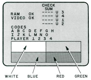
VIDEO-PINBALL INTERFACE TEST
For this test, the joystick must be disconnected and the 6-pin Molex test jack connected in its place. This jack simply simulates the permanent closure of the 4 joystick switches (one can be be easily made up if it is missing from your game). (NOTE: There must be at least 1 credit on the game before the test can be initiated.)
PART I - RAM and Video board checks/PROM checksums. PART II - Lamp and player data. PART III - Full intensity colour checks. PART I - Part I of the interface test checks the RAMS on the I/O board and the Video boards. The tests are pass/fail and will appear as either "OK" for pass, or "NO" for a failure. If the RAM check comes up "NO", the faulty board is most likely the I/O RAM board. If the Video check comes up "NO", the faulty board will most likely be the Video 3 board. The checksums are for U1-U4 on the EPROM board. The checksum numbers are not indicated on the diagaram abvove but will appear on the screen. PART II - Part II checks the lamps L4-L7 and L12-L16. The codes are sequentially sent from the pinball to the video portion and are displayed A B C....M N O. They must be displayed in that order. Refer to Chart 1 for binary information and code explanations. The player lines are similarly verified. The video section then exercises the lines back to the pinball via the switch matrix. This part of the test is displayed in the "Ball in Play" window in the lightbox. Refer to Chart 2 for binary information and code explanations. The codes sent are: Upon completion of this test, if the joystick test jack is still connected, the test will cycle through Parts I, II and III continuously. Part III - Part III is located on the bottom portion of the screen and consists of the 4 colour boxes. They are full intensity colour of red, green, blue and white. NOTE: When the test is completed, do not forget to turn off switches 6, 7 and 8 on the A1 Control board. CHART 1
L16 = Data Strobe for Code A-O
CODELAMP DATAEXPLANATION
(0 = off; 1 = on)
0001Reset game
0010Enter video play (left)
0011Enter video play (right)
01
0Change a Tyrannosauraus to a Pterodactyl
01
1Change all Pterodactyls to Tyrannosauruses
01
0Enter Extra Ball object on screen
01
1Tilt
1000Game Over
1001Remove Extra Ball object from the screen
1010Flash all Pterodactyls
1011Display English instructions
1100Display French instructions | |||||||||||||||||||||||||||||||||||||||||||||||||||||||||||||||||||||||||||||||||||||||||||||||||||||||||